


 Chinese
 Spanish
 Russian
 Portuguese
 French
 German
 Indonesian
 Thai
 Vietnamese
 Arabic
 Italian
 Turkish
 Polish
 Japanese



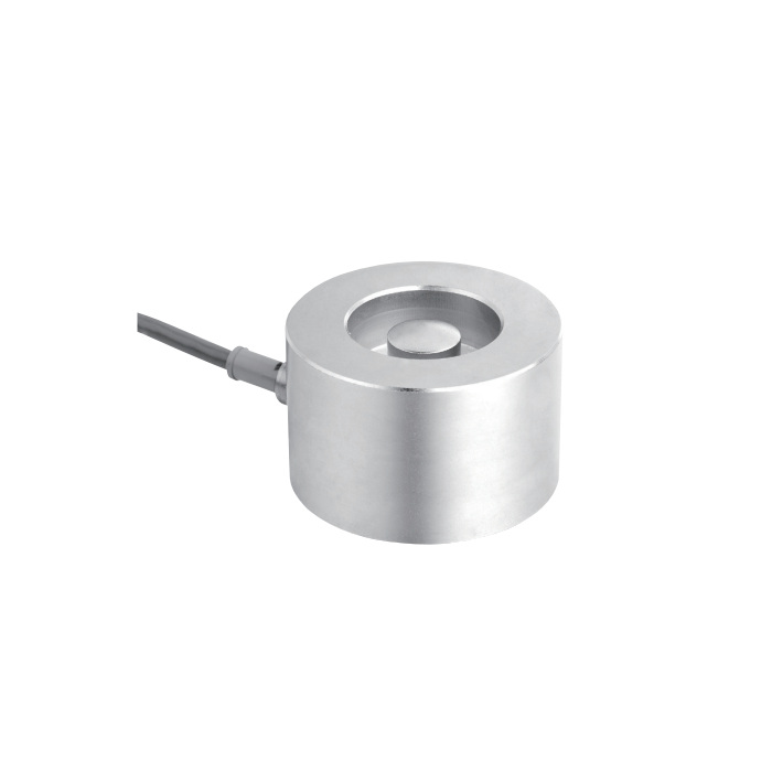
METRAVON MV-LC0165 is a compact compression load cell listed for hopper, silo and weighing-module assemblies at 0.5, 1, 2, 3 and 5 t. Selection depends on the central load contact and the complete installed height, not only the cylindrical body. Review the proposed contact parts and support arrangement with the offered version drawing.
Check the central contact before designing a compact support
The reference drawing gives an outside diameter of 67.2 mm, a 30 mm loading-contact diameter and a 46.4 mm overall height dimension; a separate 38.7 mm body-height dimension is also shown. Use the complete contact stack when setting the installation space. Confirm the delivered contact configuration from the drawing rather than estimating its depth or projection from a photograph. Adjacent support parts must not touch another portion of the body and divert the intended load.
| Item | Value | Selection notes |
|---|---|---|
| Capacity choices | 0.5, 1, 2, 3, 5 t | Select for the largest reaction at the measuring support. |
| Outside / contact diameter | 67.2 / 30 mm | Confirm the offered mating-contact arrangement. |
| Overall / body height | 46.4 / 38.7 mm | Reserve space for the complete support, not the body alone. |
| Standard cable | Four-core, 6 m; 5 mm diameter | Check routing access before closing the vessel support. |
| Excitation | 4-12 V DC; maximum 15 V DC | The raw bridge is not a direct PLC current-loop output. |
| Working temperature | -30 to +70 deg C | Review local temperature and protection of the cable connection. |
| Safe / ultimate overload | 150 / 300% FS | Overload limits are not additional permitted working capacity. |
Size the support for vessel tare and unequal reactions
Include the empty hopper, maximum contents and loads transmitted by feed equipment or pipework. Establish the highest reaction at a measuring point under the required operating states instead of dividing net contents equally among the supports. A compact compression element does not provide the complete restraint, thermal-movement or uplift functions of a weighing module. List those assembly requirements separately so that the quotation identifies both the sensor and the required mechanical hardware.
Connect the 6 m bridge lead before calibrating the channel
The standard four-core cable is 6 m long and 5 mm in diameter across the listed 0.5-5 t range. Output sensitivity is 2.0 +/-0.002 mV/V, with input resistance 650 +/-10 ohms and output resistance 610 +/-2 ohms. Check reader excitation capacity and the complete connected bridge arrangement. Complete the intended cable routing and terminations before reference loading so the accepted calibration reflects the final installation.
Observe a held load as well as the initial indication
Total error is specified as +/-0.05% FS and 30-minute creep as +/-0.03% FS. These entries address different aspects of sensor performance; they should not be added or presented as a guaranteed installed-system error without a defined assessment. For a hopper that remains loaded, agree a hold observation as well as repeated filling and empty return. Investigate contact binding, pipe forces and support movement before trying to conceal unstable readings with display filtering.
Module scope and pipework effects
Q1. Does the sensor price include a complete hopper module?
The compression sensor and a complete restrained support are different scopes of supply. Identify the contact pieces, frame, stops, uplift provisions and installation hardware on the required assembly drawing. Obtain an itemised offer rather than assuming every component is included with the sensor.
Q2. Will a larger capacity solve zero drift after pipework is connected?
Only if overload is actually the cause; a larger rating does not remove force transmitted by a stiff pipe or a binding support. Compare the empty reading before and after the relevant connections are completed, then test representative operating states. Correct the mechanical influence before accepting the channel.
