


 Chinese
 Spanish
 Russian
 Portuguese
 French
 German
 Indonesian
 Thai
 Vietnamese
 Arabic
 Italian
 Turkish
 Polish
 Japanese



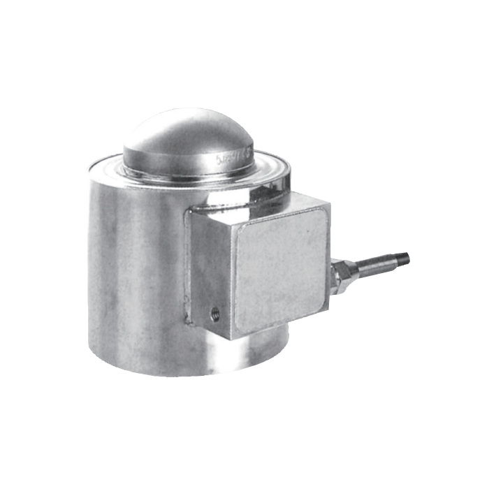
METRAVON MV-LC0164 is a column compression load cell for hopper, silo, press and weighing-module supports. The capacity list runs from 2 to 300 t, while the published dimensional rows cover 2-5 t and 10-50 t. Select the exact rating first, then obtain its contact geometry and cable configuration before approving the support assembly.
Allow for the 1 mV/V signal when retaining a reader
Rated output is 1.0 +/-0.002 mV/V. At 10 V excitation the nominal rated signal is 10 mV, half the signal of a nominal 2 mV/V bridge at the same excitation. Check the reader input range, gain and usable resolution before copying an existing setup. Input resistance is 650 +/-10 ohms and output resistance 610 +/-2 ohms; the final span must be established using this sensor and the installed load contacts.
The column compression load cell contact changes despite equal height
Both published dimensional groups give overall height H = 138.5 mm and body diameter D1 = 89 mm. However, upper contact diameter D3 changes from 24 mm at 2-5 t to 54 mm at 10-50 t, and contact radius R changes from 15 to 35 mm. A shared outer height is therefore insufficient for a replacement decision. Match the upper loading piece and lower support to the selected drawing, with clearance for the side cable housing.
| Item | Value | Selection notes |
|---|---|---|
| Capacity choices | 2, 5, 10, 20, 30, 50, 75, 100, 150, 200, 250, 300 t | Match one rating to its complete offered drawing. |
| 2-5 t H / D3 / R | 138.5 / 24 / 15 mm | These dimensions are height, contact diameter and radius. |
| 10-50 t H / D3 / R | 138.5 / 54 / 35 mm | The upper contact changes even though height is unchanged. |
| 2-5 t / 10-50 t cable | 8 / 14 m | The listed four-core lead is 5 mm in diameter. |
| 200-300 t cable | 18 m | Confirm dimensions separately for these larger versions. |
| Excitation / temperature | 4-12 V DC / -30 to +70 deg C | Maximum excitation is 15 V DC. |
Resolve the higher-capacity installation before reserving space
The list includes 75, 100, 150, 200, 250 and 300 t, but these ratings are not assigned dimensions in the two published rows. Do not extend the 89 mm body or 138.5 mm height to those versions. Standard cable notes give 8 m for 2-5 t, 14 m for 10-50 t and 18 m for 200-300 t. The 75-150 t cable arrangement needs confirmation along with the matching installation drawing.
Check changing process forces at the support, not just static weight
For a vessel, assess the highest support reaction as contents, connected piping and restraints change state. For press duty, provide the force cycle and contact arrangement rather than relying on the vessel application alone. Published total error and 30-minute creep are each +/-0.03% FS. Verify reference loading, return and any required hold condition through the assembled support; the figures do not define the accuracy of the whole machine or an unrestricted impact duty.
For a compact 0.5-5 t support, compare MV-LC0165 separately: its contact stack and nominal 2 mV/V signal are different.
Contact reuse and missing version details
Q1. Can the 2-5 t loading cap be retained for a 10 t replacement?
The reference contact diameter and radius change between those groups. Review the mating cap, contact stress and seating arrangement with the selected 10 t drawing. Equal body height does not justify keeping an incompatible upper contact.
Q2. Is the 100 t version supplied with the 14 m cable?
That length is documented for 10-50 t, not for 100 t. Obtain the delivered length and termination for the 100 t offer. Plan the reader position only after the selected sensor drawing and cable arrangement are confirmed.
Q3. Can IP68 alone settle a flooded-support installation?
Specify the anticipated water depth, duration and condition of the field connections. Obtain the relevant protection test conditions for the ordered material and construction. The sensor entry does not cover every junction box or cable joint in the installed system.
