


 Chinese
 Spanish
 Russian
 Portuguese
 French
 German
 Indonesian
 Thai
 Vietnamese
 Arabic
 Italian
 Turkish
 Polish
 Japanese



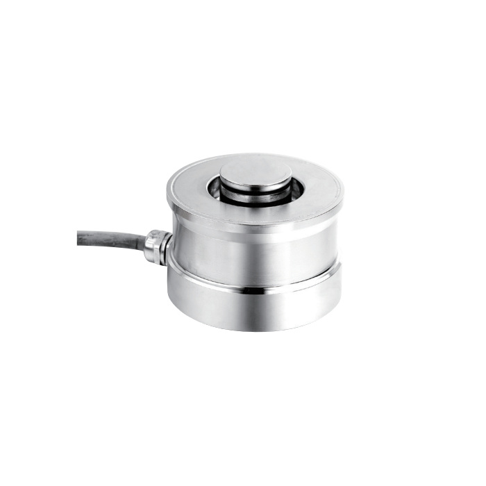
METRAVON MV-LC0163 is a compression load cell for hoppers, silos, presses and weighing-module assemblies. Force enters through its central loading surface and is reacted through the base. The cylindrical body is not a cantilever beam, and its 2.85 mV/V output must be accounted for when selecting an indicator or replacing a sensor in an existing system.
Choose the rated load and body size together
Available rated loads are 1, 2.2, 3.3, 4.7, 10, 15, 22, 33, 47, 68, 100 and 150 t. Each rating refers to an individual sensor. For a supported vessel, include tare weight, material and the maximum reaction at the most heavily loaded support. For a press, establish the force that actually passes through the sensor rather than using the actuator's nominal rating alone.
| Rated load | Diameter A | Height H |
|---|---|---|
| 10, 15, 22 t | 75 mm | 50 mm |
| 33 t | 95 mm | 65 mm |
| 47 t | 130 mm | 75 mm |
| 68 t | 130 mm | 85 mm |
| 100 t | 150 mm | 90 mm |
| 150 t | 150 mm | 100 mm |
The 1-4.7 t versions use a separate drawing. The dimensions above are selected envelope dimensions for the larger bodies, not complete installation instructions. Obtain the drawing for the quoted rating and loading accessory before preparing the support plates.
Why the 2.85 mV/V output matters
At 10 V excitation, the nominal full-scale signal is 28.5 mV, calculated from the rated sensitivity. Check that the receiving instrument can accept this signal with sufficient margin for its zero adjustment and permitted load conditions. An existing span setting for a 2 mV/V or 3 mV/V sensor will not be correct merely because the replacement has the same capacity.
| Parameter | Listed value |
|---|---|
| Sensitivity | 2.85 ±0.005 mV/V |
| Input / output resistance | 1450 ±10 / 1450 ±5 ohm |
| Excitation | 4-12 V DC; maximum 15 V DC |
| Total error / 30-minute creep | ±0.03 / ±0.03% FS |
| Operating temperature | -30 to +70 °C |
| Protection / safe overload | IP68 / 150% FS |
The relatively high bridge resistance is another reason to review the complete circuit when mixing or replacing sensors. Give the instrument supplier the sensor count, resistance and sensitivity values. Nominal full-scale signal is an interface check; final scaling must use the actual calibrated system.
Compression support and restraint
The bearing surfaces must direct the force through the intended axis without rocking or unintended edge contact. A load cell does not provide lateral restraint or uplift protection for a silo. Specify these separately in the weighing-module arrangement, while allowing the movement the installation needs. Thermal expansion and rigid pipework should not create uncontrolled side loads.
At commissioning, record zero with all permanent fittings installed, compare known loads across the working range and check the reading after unloading. For a multi-support system, also assess how the load is distributed. A combined total that looks correct at one loading point can conceal a poorly loaded support.
Compression load cell questions
Q1. Are the 47 t and 68 t versions dimensionally interchangeable?
The listed diameter is 130 mm for both, but height changes from 75 to 85 mm. The loading surface and complete mounting drawing still require comparison. Do not compensate for an unknown height difference by adding an unreviewed spacer.
Q2. Can a compression sensor hold a vessel down during uplift?
Compression measurement does not establish a tensile restraint rating. The supporting assembly needs its own retention and uplift design. Confirm the load cell's seating and zero return after any event that unloads a support.
Request an MV-LC0163 quotation with the per-support load calculation, required installed height, loading-head drawing, sensor quantity and indicator input specification. State the needed cable length explicitly.
