


 Chinese
 Spanish
 Russian
 Portuguese
 French
 German
 Indonesian
 Thai
 Vietnamese
 Arabic
 Italian
 Turkish
 Polish
 Japanese



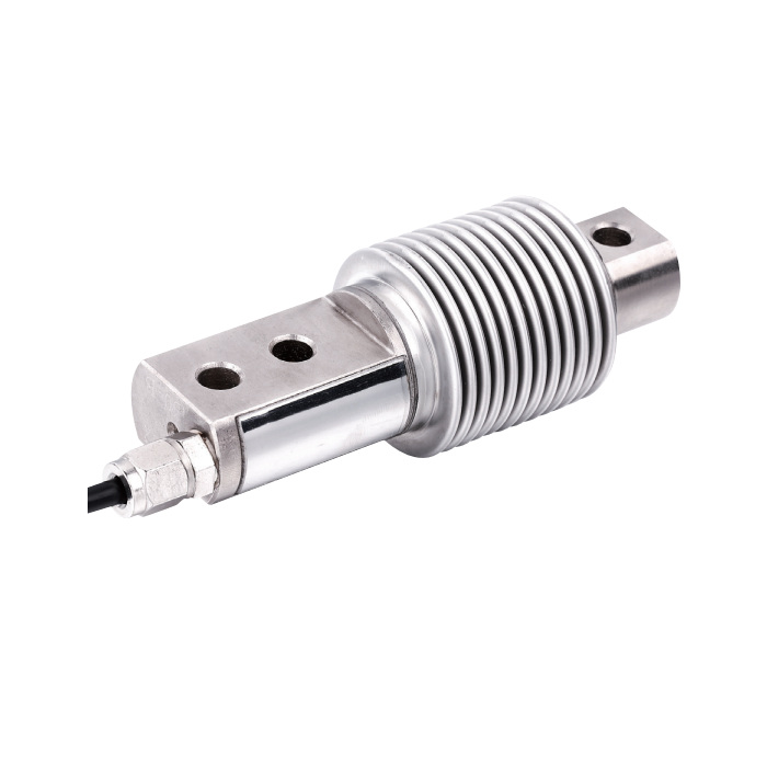
METRAVON MV-LC0162 is a bellows beam load cell with two fixing holes at one end and a separate load-introduction hole at the other. The alloy-steel design lists 15, 30, 60, 100, 150 and 300 kg ratings. It needs a beam-style support and loading arrangement, not the axial contact mounting used for a cylindrical compression sensor.
Locate the bellows beam load cell from its fixing and loading holes
The reference drawing gives a 128 mm end-to-end length, 18 mm spacing between the two fixing holes and 8.5 mm hole diameters. The inner fixing hole and loading hole are separated by 90 mm. Check the supported end, the load attachment and the clearance beneath the measuring section before making an adapter. Contact with the bellows or another part of the moving assembly can divert force or prevent the intended deflection.
Calculate the load at the measuring point before choosing a kg rating
Include the supported mechanism and contents rather than specifying net material weight alone. For an offset load, the fixture determines how forces and moments reach the sensing end; a quoted kg capacity does not establish an allowable platform size or off-centre loading envelope. Supply the lever geometry, attachment drawing and maximum operating load when requesting a sensor for a compact weighing assembly. Do not use the six listed ratings as evidence of a truck-scale duty.
Use the individual span rather than assuming exactly 2 mV/V
The rated-output entry is nominally 2.0 mV/V with a +/-10% sensitivity tolerance. That describes possible variation in rated signal, not a statement that calibrated readings have a 10% error. Input resistance is 410 +/-10 ohms and output resistance 351 +/-2 ohms. Check amplifier range and excitation loading, then set zero and span with reference loads through the installed attachment. The listed four-core cable is 3 m long and 5 mm in diameter.
| Item | Value | Selection notes |
|---|---|---|
| Rated capacities | 15, 30, 60, 100, 150, 300 kg | Choose a discrete rating for the force reaching the loaded end. |
| Reference length | 128 mm | Check both end interfaces and cable-gland clearance. |
| Fixing-hole spacing | 18 mm | The separate loading-hole location is part of the fit check. |
| Bridge input / output | 410 +/-10 / 351 +/-2 ohms | Verify the reader specifications before retaining its settings. |
| Excitation | 4-12 V DC; maximum 15 V DC | Use bridge excitation and a millivolt measuring input. |
| Working temperature | -30 to +70 deg C | Temperature capability alone does not establish ingress protection. |
Agree the installed check and environmental requirements
The table lists total error and 30-minute creep of +/-0.01% FS, together with a C3 class entry. Those entries do not certify the completed machine or define its performance under off-axis forces. Record repeated loads, unload return and the required hold interval after fastening and cable routing are complete. An ingress rating is not established in the available model specification; describe washdown, condensation or immersion exposure before accepting the offered construction.
Replacement geometry and approval documents
Q1. Can a column sensor be replaced with this part if both are rated 100 kg?
Their load paths and mounting arrangements differ. This beam needs its specified fixed end and loaded end, with clearance for the sensing section. A column sensor normally uses axial contacts. Compare the complete fixture and reference-loading procedure rather than treating the capacity label as mechanical compatibility.
Q2. Does the C3 entry approve the entire weighing machine?
No system approval follows from that entry alone. If the machine has a legal-for-trade or other approval requirement, request the applicable documents for the exact offered sensor and assembly. Check the reader, installation and jurisdictional requirements separately.
