


 Chinese
 Spanish
 Russian
 Portuguese
 French
 German
 Indonesian
 Thai
 Vietnamese
 Arabic
 Italian
 Turkish
 Polish
 Japanese



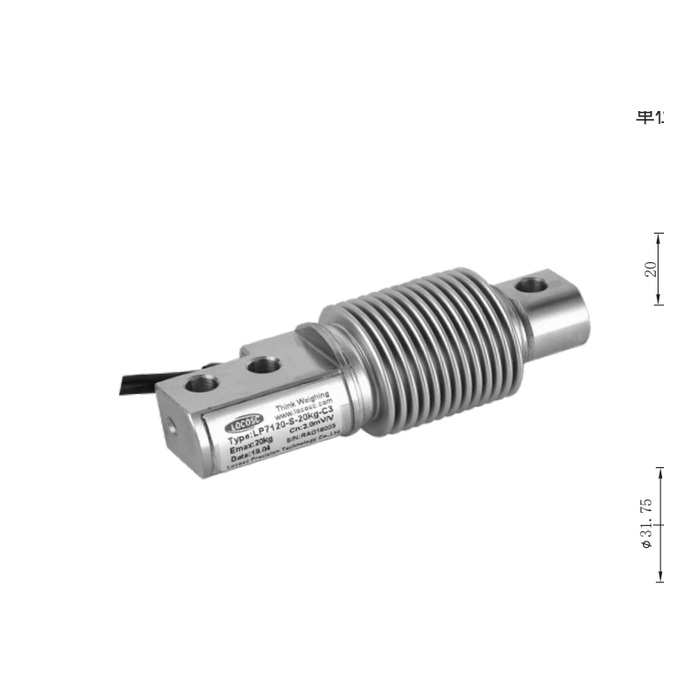
METRAVON MV-LC0161 is a bellows beam load cell for platform, pallet and weighing-module assemblies from 5 to 500 kg. The available ratings are 5, 10, 20, 30, 40, 50, 75, 100, 150, 200, 250, 300 and 500 kg. Two dimensional groups separate 5-200 kg from 250-500 kg, so the common 120 mm length does not establish identical mounting across the range.
Choose the bellows beam load cell fixing group before machining
At 5-200 kg the mounting-hole dimension d is 8.2 mm and loaded-end dimensions D and H are 23 and 20 mm. At 250, 300 and 500 kg these become 10.2, 24 and 19 mm respectively. The larger rating therefore changes both the mounting holes and the loaded-end envelope. Compare the complete drawing with the support and loading attachment instead of drilling the old pattern and assuming the new part fits.
| Item | Value | Selection notes |
|---|---|---|
| 5-200 kg fixing d | 8.2 mm | Use this mounting group only for its documented capacities. |
| 5-200 kg D / H | 23 / 20 mm | These loaded-end dimensions do not define the mounting-hole diameter. |
| 250-500 kg fixing d | 10.2 mm | The fixed-end hole size changes at the higher group. |
| 250-500 kg D / H | 24 / 19 mm | Review clearance and loading attachment height together. |
| Body length | 120 mm | The shared length is not a complete interchangeability check. |
| Excitation | 4-12 V DC; maximum 15 V DC | The reader needs a bridge input, not a direct 24 V field connection. |
| Working temperature | -30 to +70 deg C | Confirm material and protection of the completed field connections. |
Review the two ends and cable relief as one assembly
The reference centres use an 18 mm mounting pitch and 82 mm from the inner mounting centre to the loading centre. Keep the bellows and loaded section clear of neighbouring parts. The cable-end relief and its surrounding bracket need enough space for routing without forcing the cable against the support. Do not remove material from the sensor or use the bellows to restrain rotation during assembly. Obtain the intended fastening and load-introduction instructions before installing a replacement.
Check the bridge specification as well as nominal sensitivity
Output is 2.0 +/-0.002 mV/V, input resistance 400 +/-20 ohms and output resistance 351 +/-2 ohms. The four-core lead is listed at 3 m long and 5 mm diameter. Confirm the indicator excitation budget and calibration method for the complete sensor arrangement. Identical nominal 2 mV/V labels on two beam models do not establish matching mountings or an unchanged installed span; reference loading is still required after the mechanical work.
Verify the load positions that matter to the platform
Identify tare, maximum contents, uneven loading and the highest reaction at each support before choosing capacity. After assembly, record zero and apply reference loads at the agreed positions, checking repeat readings and unloaded return. For sustained loads, include the observation period appropriate to the process; 30-minute creep is specified as +/-0.02% FS. Check that restraints, stops and pipe or cable connections do not take over part of the load as the platform moves.
MV-LC0160 is another 120 mm bellows beam, but its three 8.2 mm hole arrangement must be compared with the capacity-specific mounting of MV-LC0161.
The 200 kg to 250 kg mounting change
Q1. Will a 250 kg unit fit the 200 kg mounting because both are 120 mm long?
The mounting-hole diameter changes from 8.2 to 10.2 mm, while loaded-end dimensions D and H also change. Review the new fasteners, support and loading attachment using the 250 kg drawing. Equal length alone is not a replacement approval.
Q2. Are the d and D dimensions interchangeable hole sizes?
No. The drawing assigns d to the two mounting holes and D to the loaded-end geometry. Keep those labels with their drawing features when preparing the base and attachment. If the loading connection is not clear from the supplied installation drawing, resolve it before manufacture.
