


 Chinese
 Spanish
 Russian
 Portuguese
 French
 German
 Indonesian
 Thai
 Vietnamese
 Arabic
 Italian
 Turkish
 Polish
 Japanese



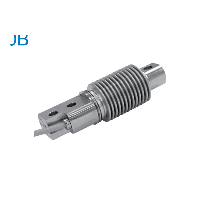
METRAVON MV-LC0160 is a compact bellows beam load cell with two mounting holes at the cable end and a separate loading hole at the opposite end. Thirteen ratings cover 5, 10, 20, 30, 40, 50, 75, 100, 150, 200, 250, 300 and 500 kg. Use it in a reviewed beam-style weighing assembly, not as a drop-in axial column sensor.
Mount the compact bellows beam load cell from the actual hole centres
The drawing gives a 120 mm body length, an 18 mm pitch between the two mounting holes and an 82 mm distance from the inner mounting-hole centre to the loaded-hole centre. All three holes are marked 8.2 mm in diameter. Confirm the support face, loading attachment and available deflection clearance together. The bellows must remain free of contact with guards or surrounding structure; a housing around the measuring section is not an extra mounting surface.
Account for the assembly tare at the lower kg ratings
The load cell carries the force applied by the assembled mechanism as well as the material being weighed. Establish the actual reaction with platform tare, load position and any leverage included. At a low-capacity measuring point, cable stiffness or friction at the load attachment can affect a small required weight change. Support the cable independently and compare readings as the mechanism moves through its operating positions, including an empty return. Do not infer an allowable platform size from the compact body.
| Item | Value | Selection notes |
|---|---|---|
| Lower kg options | 5, 10, 20, 30, 40, 50, 75, 100 kg | Check tare and the smallest useful change at the measuring point. |
| Higher kg options | 150, 200, 250, 300, 500 kg | Use the exact capacity and matching calibration record. |
| Body length / mounting pitch | 120 / 18 mm | Add room for the cable entry and attachment movement. |
| Inner mount to loaded centre | 82 mm | Changing the support arrangement changes the beam installation. |
| Hole diameter | Three 8.2 mm holes | Use the complete drawing rather than an approximate adapter. |
| Excitation / temperature | 4-12 V DC / -30 to +70 deg C | Maximum bridge excitation is 15 V DC. |
Check the complete bridge channel before accepting the bench scale
The listed cable is four-core, 3 m long and 5 mm in diameter. Sensitivity is 2.0 +/-0.002 mV/V, with input resistance 400 +/-10 ohms and output resistance 351 +/-2 ohms. Match the indicator excitation and input, then record zero, reference loading and repeat results with the final cable and attachments. Include an observation under held load if required; the published 30-minute creep entry is +/-0.02% FS. A higher display resolution does not by itself establish that the assembly can resolve the requested small load.
Low-capacity duty and field installation
Q1. Can this be used as a truck-scale sensor because a broad application list mentions vehicle weighing?
The listed individual ratings stop at 500 kg. An application label does not establish suitability for vehicle wheel loads, impact or the mechanical arrangement of a truck scale. Base selection on the calculated reaction and the approved assembly; do not substitute this low-capacity beam for a heavy column sensor.
Q2. Should a larger rating be chosen to remove low-load instability?
First determine whether tare, overload, friction, cable forces or the reader is causing the problem. A larger rating can reduce the signal change produced by a small load relative to full scale. Select capacity with both peak reaction and minimum useful weight change in view, then test the installed channel.
Q3. Does IP68 confirm protection of a field cable splice?
No conditions for an added splice follow from the sensor housing entry. Obtain the relevant sensor protection conditions and specify the cable joint or enclosure for the actual exposure. Keep the termination away from an unassessed wet location.
