


 Chinese
 Spanish
 Russian
 Portuguese
 French
 German
 Indonesian
 Thai
 Vietnamese
 Arabic
 Italian
 Turkish
 Polish
 Japanese



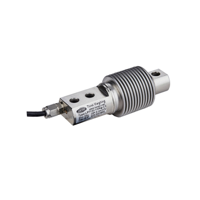
METRAVON MV-LC0159 is a bellows bending beam load cell with individual rated capacities from 5 to 500 kg. It measures through a beam supported at one end and loaded at the other; the corrugated enclosure protects the sensing section. This is not a compression column for heavy vehicle scales. It is suited to lower-capacity weighing assemblies where the beam can deflect freely and the load attachment matches the drawing.
Keep the bellows clear of the weighing structure
Use the mounting holes and load point to transmit force. Do not clamp the corrugated enclosure or allow a guard, cable or platform edge to press against it. Such contact creates a second load path and can change the reading as the platform moves. Allow access for cleaning and inspection without using the bellows as a handle or a support.
The drawing shows a 120 mm body length and an 82 mm distance from the loading-hole centre to the outer fixing-hole centre. The two fixing-hole centres are 18 mm apart. Hole diameter changes with capacity: a replacement can look identical but require different mounting hardware.
| Rated-load options | Hole diameter D |
|---|---|
| 5, 10, 20, 30, 40, 50, 75, 100, 150, 200, 250 kg | 8.2 mm |
| 300, 500 kg | 10.2 mm |
Bellows load cell output and capacity selection
For a small platform, include its own weight when calculating the support load. Then consider the highest load at one sensor when material is placed away from the centre. Choosing the largest rating simply to avoid overload can leave less usable signal for small weight changes. Define the required weighing increment and confirm it with the complete platform and electronics.
| Electrical or construction item | Specification |
|---|---|
| Rated output | 2.0 ±0.002 mV/V |
| Excitation | 4-12 V DC; maximum 15 V DC |
| Nominal input resistance | 400 ohm |
| Output resistance | 351 ±2 ohm |
| Safe overload | 150% FS |
| Material options / protection | Alloy steel or stainless steel / IP68 |
The bridge output requires an instrument input intended for load cells. When several sensors share an excitation supply, check the combined bridge load against the indicator's permitted input arrangement. Specify cable lengths and shielding with the installation so the connection design is settled before calibration.
For service with temperature changes or prolonged static loads, request the operating-temperature and creep limits for the supplied version before setting the acceptance criteria. Those limits should appear on the order-specific data sheet. IP68 alone does not establish suitability for cleaning chemicals, steam or repeated high-pressure washing.
Checks after assembly
Apply a known load at the positions the platform will actually use, not only at its centre. Compare the readings and observe whether zero returns after unloading. A reading that changes when a guard is moved or a cable is repositioned calls for a mechanical check before a span adjustment. For dosing, include a hold period and an unload cycle that represent the process.
Questions about the bellows design
Q1. Is the bellows intended to carry a vertical load directly?
No. Apply force at the specified loading point while securing the fixed end. Pressing on the enclosure bypasses the designed connection and can damage it. A central compression-load arrangement needs a different sensor and mounting design.
Q2. Does a low rated capacity guarantee fine weighing resolution?
It increases the fraction of full-scale signal produced by a given load, but resolution also depends on noise, instrument settings and the platform's mechanical behaviour. State the smallest useful weight change and verify stable readings under operating conditions.
Enquire about MV-LC0159 for your weighing assembly with the platform weight, maximum load, support layout, available mounting space and required weighing increment. Include temperature and cleaning conditions when requesting the version-specific data sheet.
