


 Chinese
 Spanish
 Russian
 Portuguese
 French
 German
 Indonesian
 Thai
 Vietnamese
 Arabic
 Italian
 Turkish
 Polish
 Japanese



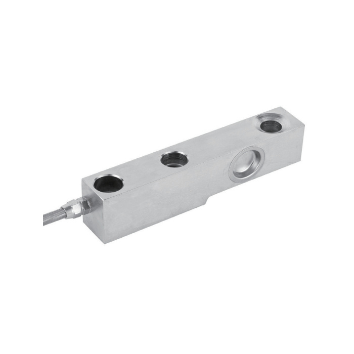
METRAVON MV-LC0158 is a shear beam load cell for platform and pallet scales, offered at 500 kg and 1, 2, 3 or 4 t. Two rated-output entries are listed: 1.5 +/-0.002 mV/V and 2.0 +/-0.002 mV/V. The output version must be confirmed on the offer rather than assigned from capacity or selected later as an indicator setting.
Specify the shear beam load cell output before retaining an old indicator
At 10 V excitation, nominal full-scale signal is 15 mV for a 1.5 mV/V unit and 20 mV for a 2 mV/V unit. The same capacity number therefore does not mean the old span calibration remains correct. Obtain the actual output version and check reader range and calibration adjustment. Where several sensors feed a junction arrangement, review their capacity and signal-matching requirements with the measuring electronics rather than mixing nominal outputs without assessment.
| Item | Value | Selection notes |
|---|---|---|
| Rated choices | 500 kg; 1, 2, 3, 4 t | Output version is a separate order confirmation. |
| First output entry | 1.5 +/-0.002 mV/V | At 10 V excitation the nominal rated signal is 15 mV. |
| Second output entry | 2.0 +/-0.002 mV/V | At 10 V excitation the nominal rated signal is 20 mV. |
| Body length | 175 mm | Obtain the full fixing and recess drawing before machining. |
| 500 kg-2 t width A | 30.3 mm | Check the corresponding base and contact clearances. |
| 3-4 t width A | 36.6 mm | Do not retain the lower-group width by assumption. |
| Excitation | 4-12 V DC; maximum 15 V DC | The listed outputs are raw bridge sensitivities, not volt signals. |
Compare the width group and recessed loading contact
The reference body length is 175 mm. Width A is 30.3 mm for 500 kg, 1 t and 2 t, increasing to 36.6 mm for 3-4 t. The drawing also defines the loading recess, countersinks and fixing positions. Compare the mating contact and base geometry from the complete drawing; an overall length match does not make a narrower support or a different insert suitable. The 120-degree recess callout describes a surface angle, not a permissible angle of sensor movement.
Set up the 3 m bridge connection and test load positions
The four-core cable is listed at 3 m long and 5 mm diameter. Input and output resistances are 385 +/-10 and 351 +/-2 ohms. Verify excitation demand for the connected bridges and set zero with the final contacts and fasteners installed. Establish span with the correct rated output, then compare the load positions required by the platform design. Investigate a binding contact or uneven reaction before applying junction adjustments to hide the mechanical influence.
Make the enquiry distinguish the sensor from the scale assembly
Include platform tare, maximum load, support count, largest individual reaction, load positions and the intended contact hardware. State the actual temperature and water exposure at the sensor. The listed working range is -30 to +70 deg C, with alloy-steel or stainless-steel versions and IP67. No platform size or permitted off-centre loading envelope is defined by the beam length alone. Request the assembly scope and suitable calibration information with the sensor quotation.
Output assignment and width changes
Q1. Is the 4 t version always the 2 mV/V version?
The specification does not assign one rated output to each capacity. Request the offered sensitivity and calibration information for the exact 4 t configuration. Do not choose the amplifier span or combine sensors on the assumption that the larger capacity determines the output.
Q2. Can a 3 t replacement reuse a 2 t mounting because both are 175 mm long?
The width changes from 30.3 to 36.6 mm between those groups. Inspect the complete fastening and load-contact details as well as available clearance. Retaining the old base requires a dimensional review, not just a shared body length.
