


 Chinese
 Spanish
 Russian
 Portuguese
 French
 German
 Indonesian
 Thai
 Vietnamese
 Arabic
 Italian
 Turkish
 Polish
 Japanese



METRAVON MV-LC0157 is a threaded-end beam load cell for platform scales, pallet scales and weighing assemblies. It lists two capacities: 500 kg and 1 t. The loading attachment uses an M12 thread at one end, while two through-holes secure the supported end. Review the attachment and support as a beam assembly rather than treating the threaded hole as proof of a tension-sensor rating.
Fit the threaded-end beam load cell without changing its support span
The drawing specifies 130 +/-0.1 mm body length, 30.5 mm width and 19 mm height. The two fixing holes are 13.5 mm in diameter on 25.4 mm centres. A 76.2 mm dimension locates the loading-thread centre relative to the nearer fixing-hole centre. Check these relationships on the base and loading attachment before drilling an adapter. Clamping another portion of the beam or allowing the moving structure to touch it can change the force reaching the sensing section.
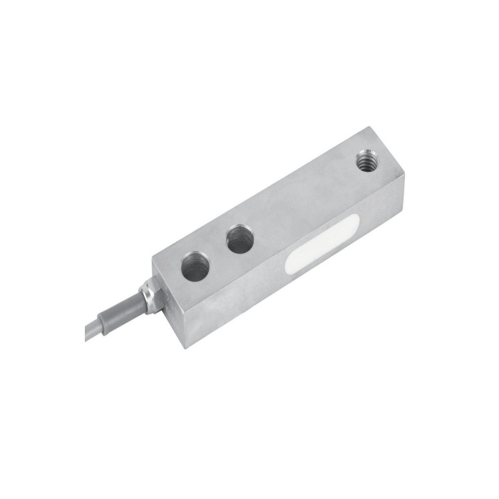
Approve the M12 attachment before setting zero
The load-end designation is M12; no pitch or permitted engagement is established by that designation alone in the model drawing. Obtain the mating thread and installation requirements for the offered version. Provide the direction of force, attachment offset and any process reversal so the configuration can be checked. Assemble and lock the intended load attachment before recording zero, then inspect repeat readings and the unloaded return with that attachment in place.
Use the final cable and platform when calibrating
A four-core 3 m cable of 5 mm diameter is listed, with output sensitivity 2.0 +/-0.002 mV/V. The bridge input is 385 +/-10 ohms and output 351 +/-2 ohms. Verify the reader input and complete the installed route before establishing span. For a multi-support platform, compare the agreed load positions as well as the central reference load; one correct central reading does not verify the other positions. The 30-minute creep figure is +/-0.02% FS, which is a sensor characteristic rather than an acceptance limit for every completed scale.
| Item | Value | Selection notes |
|---|---|---|
| Capacity options | 500 kg, 1 t | No 2 t rating is established by the capacity list. |
| Body length | 130 +/-0.1 mm | Reserve additional clearance for the cable exit. |
| Width / height | 30.5 / 19 mm | Compare the mounting face and loaded-end clearance. |
| Fixing holes / pitch | 13.5 / 25.4 mm | Use the complete two-hole pattern, not only its diameter. |
| Loading connection | M12 | Confirm pitch, engagement and allowed force direction. |
| Excitation | 4-12 V DC; maximum 15 V DC | Select a reader with bridge excitation and millivolt input. |
| Working temperature | -30 to +70 deg C | Confirm the ordered material and field connection protection. |
Listed capacities and threaded loading
Q1. Does the cable note mentioning 2 t create a third capacity?
No. The model capacity list identifies 500 kg and 1 t only. A cable-group note is not evidence that a 2 t sensor with the same geometry is available. Request a separately confirmed model and drawing if the application exceeds the listed capacity.
Q2. Can an M12 rod be used for a suspended load without further checks?
A threaded attachment does not establish a rated tensile assembly or a permitted reversal. Provide the suspension arrangement, required force direction and consequences of a connection failure. Obtain the applicable sensor and attachment confirmation before using that arrangement.
Q3. Will C3 alone establish the finished platform accuracy?
The class entry does not replace the installed reference-loading test or the documents required for a particular weighing system. Define the required load interval, resolution and acceptance procedure, including positional checks where relevant. Confirm the result with the final platform, contacts and reader.
