


 Chinese
 Spanish
 Russian
 Portuguese
 French
 German
 Indonesian
 Thai
 Vietnamese
 Arabic
 Italian
 Turkish
 Polish
 Japanese



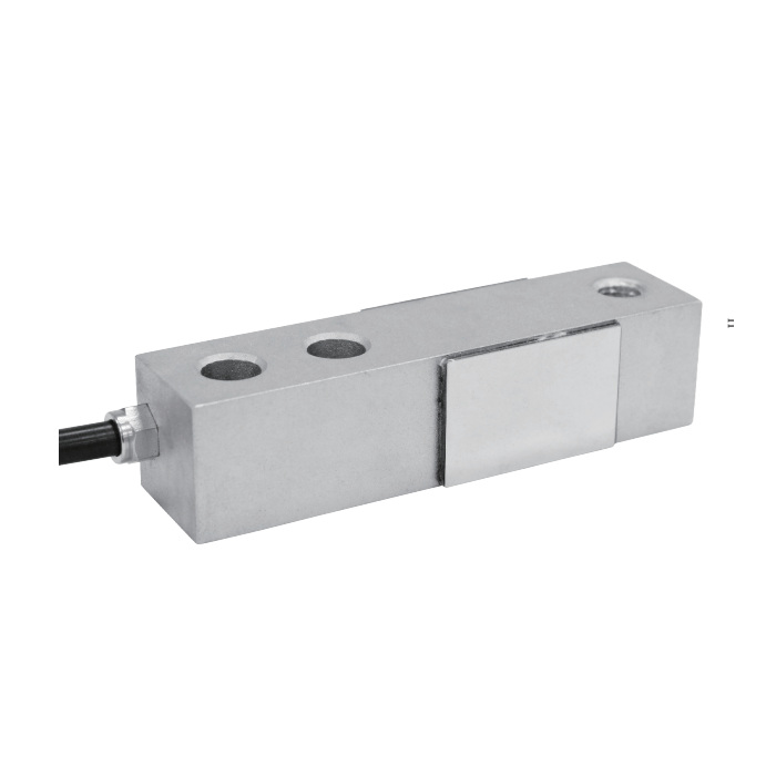
METRAVON MV-LC0153 is a threaded shear beam load cell for platform, pallet and weighing-module arrangements. Capacities are 100, 200, 250 and 500 kg plus 1, 1.5, 2, 2.5, 3, 5, 7.5 and 10 t. The loaded end and fixed-end support must match the chosen size group; the common electrical sensitivity does not make the mechanical versions interchangeable.
Start the threaded shear beam load cell replacement at the loaded end
The lower group through 2.5 t has a 130 mm reference length, 31.8 mm height and an M12 loading designation. The 3-5 t group increases to 171.5 mm length and 38.1 mm height with M20 x 1.5; 7.5-10 t uses 222.3 mm length and 50.8 mm height with M24 x 2. Obtain the pitch for an M12 order instead of assuming it from the diameter. Compare the mating foot and the supporting structure before changing capacity.
| Item | Value | Selection notes |
|---|---|---|
| kg ratings | 100, 200, 250, 500 kg | The 100 kg and 200 kg cable length needs confirmation. |
| t ratings | 1, 1.5, 2, 2.5, 3, 5, 7.5, 10 t | Use the matching thread, fixing pattern and height group. |
| Lower / middle / upper pitch | 25.4 / 38.1 / 50.8 mm | These are fixed-end fixing centres. |
| Lower / middle / upper L3 | 76.2 / 95.3 / 120.7 mm | Compare the loading-point location on the actual drawing. |
| Bridge input / output | 385 +/-10 / 351 +/-2 ohms | Check the available excitation for all connected channels. |
| Excitation | 4-12 V DC; maximum 15 V DC | Use a millivolt bridge reader or suitable conditioner. |
| Working temperature | -30 to +70 deg C | Confirm IP67 or IP68 for the actual ordered construction. |
Check fixed-end holes and the effective support span
The documented fixing pitch grows from 25.4 to 38.1 and 50.8 mm across the groups. The associated L3 distances are 76.2, 95.3 and 120.7 mm. Keep the fixed-end seating surface and loaded-end clearance consistent with the selected drawing. An adapter that adds unintended support beneath the measuring section can change the force path even when its holes align. Include the base stiffness, bolt arrangement and required installation instructions in the mechanical review.
Plan the cable from the confirmed metric configuration
The metric cable groups give 3 m for 250 kg-2.5 t and 6 m for 3-10 t. Confirm the supplied length for the listed 100 kg and 200 kg options. Do not create additional imperial capacity choices from imperial references in a cable note. The lead is four-core and 5 mm in diameter, with a nominal 2 mV/V bridge signal. Complete the cable route and connections before calibrating the final reader.
Measure the platform response where the load will actually sit
State the tare, full load, load positions and maximum reaction at each support. After assembly, compare reference readings at the positions needed for the application, repeat selected loads and inspect unloaded return. The 30-minute creep entry is +/-0.02% FS; specify any required hold observation separately. Keep an approval requirement, permissible installed error and display resolution as distinct enquiry items rather than treating the C3 entry as proof that the finished scale meets all three.
Crossing the 2.5 t to 3 t size boundary
Q1. Can a 3 t sensor replace a 2.5 t part without changing the mounting?
The listed transition changes length, height, thread and fixing geometry. Review the complete support and loading foot with the 3 t drawing before approving the change. A capacity increase does not itself upgrade the adjacent structure or preserve the scale level.
Q2. Is an M12 loading designation enough to order a threaded foot?
It leaves pitch and engagement requirements unresolved. Obtain the offered installation drawing and mating-thread requirements before manufacturing or reusing the foot. Do not transfer a pitch from a different beam merely because its body is also 130 mm long.
