


 Chinese
 Spanish
 Russian
 Portuguese
 French
 German
 Indonesian
 Thai
 Vietnamese
 Arabic
 Italian
 Turkish
 Polish
 Japanese



METRAVON MV-LC0152 is a necked-end beam load cell listed for platform scales and weighing modules at 1, 2, 2.5, 3 and 5 t. Its shaped loading end needs a compatible mating component. It is not a threaded-load-end beam, and a similar body length does not justify transferring an attachment from another sensor design.
Match the necked-end beam load cell to the mating support
Review the neck, end profile and opposing contact with the support drawing. The reference drawing gives different neck and contact dimensions for the two capacity groups. Obtain the delivered interface details before making a socket or load-bearing adapter. A curved neck does not establish a ball joint, unrestricted rotation or a permitted lateral displacement. The complete module must provide its required movement and restraints without applying an unreviewed side force to the measuring beam.
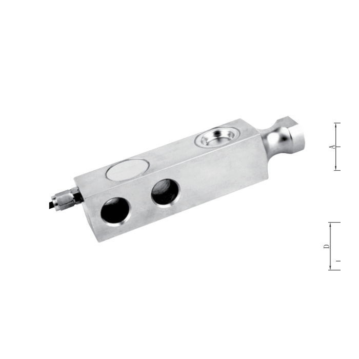
Use the fixing dimensions for the actual capacity group
The 1-2.5 t row gives 130 mm body length, 25.4 mm fixing pitch and 13.5 mm fixing-hole diameter. The 3-5 t row gives 171.5 mm length, 38.5 mm pitch and 20 mm holes. The corresponding L3 dimensions are 76.2 and 93.5 mm. Keep these values with this model drawing rather than copying the superficially similar 38.1 mm and 95.3 mm values from a different beam. Confirm the final installation drawing before machining a replacement support.
| Item | Value | Selection notes |
|---|---|---|
| Capacity list | 1, 2, 2.5, 3, 5 t | The cable note does not establish a separate 500 kg option. |
| 1-2.5 t length / pitch | 130 / 25.4 mm | The fixed-end holes are 13.5 mm in diameter. |
| 3-5 t length / pitch | 171.5 / 38.5 mm | Use the documented 20 mm holes and matching base. |
| Lower / upper group L3 | 76.2 / 93.5 mm | Retain the values from this version drawing. |
| Standard cable groups | 3 / 6 m | Route the lead independently of the loaded contact. |
| Excitation | 4-12 V DC; maximum 15 V DC | No current-loop or serial output is specified at the sensor. |
| Working temperature | -30 to +70 deg C | Confirm material and the offered ingress-protection version. |
Finish the contact assembly before electrical acceptance
Cable length is 3 m for the listed 1-2.5 t ratings and 6 m for 3-5 t, with four cores and 5 mm diameter. Sensitivity is 2.0 +/-0.002 mV/V; input resistance is 385 +/-10 ohms and output resistance 351 +/-2 ohms. Select the reader for the installed bridge arrangement, then verify zero, reference loads and repeat behaviour through the final shaped contact. Check that the mating support remains clear through the intended movement instead of adjusting the indicator to compensate for binding.
Contact adapters and permitted movement
Q1. Can a threaded weighing foot be fitted directly to the shaped end?
The reference configuration uses a necked contact rather than the central loading thread of another beam. A mating adapter needs its own reviewed geometry and load path. Do not improvise a conversion from the body length or nominal capacity.
Q2. Does the 500 kg entry in the cable note establish an available rating?
The capacity table starts at 1 t. If 500 kg is required, obtain a separately confirmed offered model and its drawing rather than treating the cable-group boundary as a product capacity.
Q3. Is the curved end enough to accommodate vessel thermal movement?
Its shape alone does not define permitted travel, rotation or side-load capacity. Provide the expected movement and required restraint functions with the complete module layout. Acceptance should verify the intended load path at the relevant operating positions.
