


 Chinese
 Spanish
 Russian
 Portuguese
 French
 German
 Indonesian
 Thai
 Vietnamese
 Arabic
 Italian
 Turkish
 Polish
 Japanese


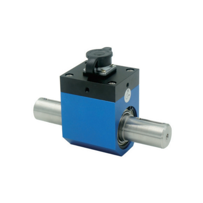

METRAVON MV-LC0148 is a rotary torque sensor with keyed shafts at both ends and discrete ratings from 0.1 to 500 N m. It is assessed for a rotating test rig by the torque to be measured, the speed and the mechanical connection to the drive and load. Include start-up and braking peaks when defining the torque duty, and compare both coupling interfaces with the selected shaft drawing. Define the torque duty, shaft arrangement and receiving acquisition system before choosing the rating.
Select the rotary torque sensor for working torque and transients
The listed ratings are 0.1, 0.2, 0.3, 0.5, 1, 2, 3, 5, 10, 20, 30, 50, 100, 200, 300 and 500 N m. State continuous working torque, reversals and start or stop events as applicable to the rig. The reference supports positive and negative torque signals, but the required signed calibration and controller scaling must be agreed. Its 120% FS safe-overload entry is not a routine working margin, and the 150% FS ultimate figure is not a permissible test target. Check the entire shaft train separately.
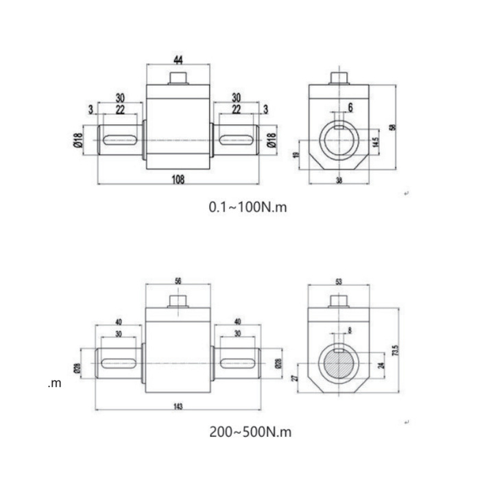
Use the coupling envelope for the chosen torque group
The 0.1-100 N m outline shows 18 mm shafts and a 108 mm longitudinal reference; its key-width reference is 6 mm. The 200-500 N m outline changes to 28 mm shafts, 143 mm longitudinal reference and an 8 mm key-width reference. Confirm shaft fits, key details, engagement and the full rated housing outline before making couplings. A matching key width alone does not approve the coupling or its torque rating. Reserve axial assembly space and access to the connector and any support arrangement.
| Item | Value | Selection notes |
|---|---|---|
| 0.1-100 N m outline | 18 mm shafts / 108 mm length | 6 mm key-width reference; confirm shaft fit and engagement. |
| 200-500 N m outline | 28 mm shafts / 143 mm length | 8 mm key-width reference; review the larger coupling envelope. |
| Speed boundary | No more than 4000 r/min | Confirm the actual rated duty and complete rotating installation. |
| Recommended / maximum excitation | 12 / 15 V | Neither value establishes compatibility with a 24 V process input. |
| Sensitivity reference | 1.0-1.5 mV/V | Obtain actual build, calibration and receiving-channel requirements. |
| Safe / ultimate overload entries | 120 / 150% FS | Do not use the ultimate value as an operating or proof-load target. |
Confirm rotation limits without inferring an rpm output
The stated maximum speed does not exceed 4000 r/min. Confirm the allowable duty for the actual rating and installation rather than assuming every rig can run continuously at that boundary. Provide the coupling, shaft-support and rotational arrangement for review, including any radial or axial loading. A rotary torque product is not automatically a tachometer, and the presence of a speed limit does not establish a separate speed channel. Do not specify a pulse, frequency or digital protocol without a delivered interface document.
Resolve the electrical build before connecting the test system
The technical output reference is 1.0-1.5 mV/V. Recommended excitation is 12 V and maximum excitation is 15 V; a generic 24 V process supply must not be assumed compatible. The impedance entries list 350/700 ohm alternatives with +/-10 ohm tolerance, so identify the supplied configuration and actual sensitivity. Request terminal functions, acquisition requirements, scaling and calibration information together. The available data do not establish a direct RS485 or current-loop input connection to a PLC.
Accept the torque chain with the final couplings installed
Verify zero, signed response and agreed reference torque using the approved test and guarding procedure. Check repeated values and the return after unloading for the directions used in service. Non-linearity and hysteresis are each +/-0.2% FS, while repeatability is +/-0.1% FS. Keep those definitions separate from a complete rig accuracy requirement. Compensation is listed at -10 to +60 deg C and operation at -20 to +60 deg C, with IP66. Output and zero temperature effects are each +/-0.02% FS per 10 deg C. Record the delivered configuration and torque reference with the final coupling arrangement.
Coupling changes, speed channels and overload figures
Q1. Can a 100 N m sensor be changed to 200 N m without replacing couplings?
The reference shaft diameter changes from 18 to 28 mm and the longitudinal envelope also changes. Review both couplings, shaft positions, available space and the complete torque chain before choosing the higher rating.
Q2. Does the 4000 r/min limit mean that speed is measured as well as torque?
No separate speed output is established by that limit. Identify the required speed measurement and request an explicitly documented channel or separate instrument where needed.
Q3. Can the 150% FS ultimate entry be used for a routine torque check?
It is not a permitted working or routine verification load. Agree a suitable reference-torque procedure within the approved installation limits and keep the sensor, couplings and surrounding rig ratings separate.
