


 Chinese
 Spanish
 Russian
 Portuguese
 French
 German
 Indonesian
 Thai
 Vietnamese
 Arabic
 Italian
 Turkish
 Polish
 Japanese



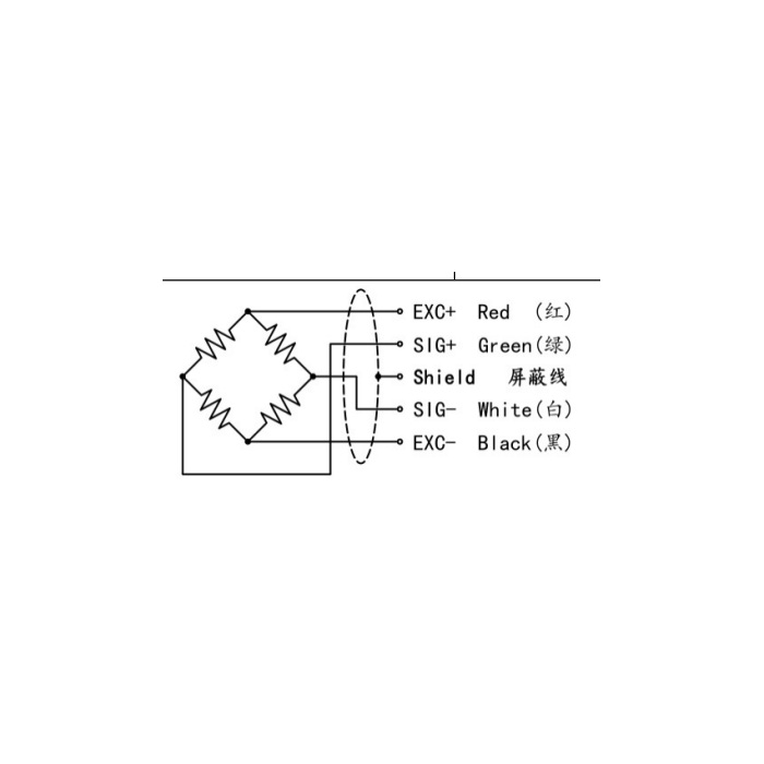
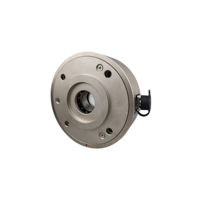
METRAVON MV-LC0147 is a through-shaft tension load cell with an integral bearing for use around a roller shaft. In a winding or unwinding installation, it measures the reaction transmitted through the roller support. The controller can represent web tension only when the web path, roller weight and support arrangement are accounted for. Select the bearing bore and rated reaction together rather than treating the nominal load class as the web-tension setting.
Describe the roller and web path before selecting the sensor
Provide the roller drawing, supported weight, shaft dimensions, web entry and exit directions, and the useful tension interval. State whether one or both roller supports are measured and what other restraints act on the shaft. The support reaction depends on that arrangement and may include forces unrelated to the desired web tension. The monitoring system therefore needs a defined mechanical relationship and calibration procedure; it cannot infer tension from a nominal kilogram rating alone.
Confirm the through-shaft load cell version at overlapping sizes
The mechanical table contains a 30-50 kg group with a 17 mm G bore, a 75-100 kg group with 25 mm, a 150-300 kg group with 35 mm and a 300-600 kg group with 50 mm. The two groups meeting at 300 kg have different housings and bores. The technical range is stated separately as 10-1000 kg, while additional dimensional rows extend beyond it. Those extra rows do not establish a confirmed higher-range product offer. Request one rated drawing with bore, fixing pattern, width, bearing requirements and permitted loads before ordering.
| Item | Value | Selection notes |
|---|---|---|
| 30-50 kg group: A / G / H | 105 / 17 / 36.5 mm | Four 6.5 mm fixing-hole references; confirm the rated drawing. |
| 75-100 kg group: A / G / H | 125 / 25 / 47.5 mm | Four 6.5 mm fixing-hole references; check the shaft fit. |
| 150-300 kg group: A / G / H | 175 / 35 / 65 mm | Four 8.5 mm fixing-hole references; compare the actual housing. |
| 300-600 kg group: A / G / H | 225 / 50 / 75 mm | Four 10.5 mm fixing-hole references; 300 kg appears in two groups. |
| Technical load-class interval | 10-1000 kg | Do not extend the confirmed range from additional dimensional rows. |
| Bridge / excitation | 2.0 +/-0.05 mV/V / 5-12 V | Scale roller reaction separately from the final web-tension quantity. |
Use a bridge input and retain the separate error definitions
The signal reference is 2.0 +/-0.05 mV/V at 5-12 V excitation, with 380 +/-30 ohms input and 350 +/-5 ohms output resistance. Use a suitable bridge channel or defined conditioner rather than assuming a direct process output. Non-linearity and hysteresis are each listed at +/-0.5% FS; repeatability is +/-0.3% FS. These entries must not be collapsed into the smallest number and advertised as total accuracy. Compare the complete acquisition and mechanical conversion with the required tension changes.
Assess bearing duty and environmental conditions separately
An integral bearing does not establish an unlimited shaft speed, axial load or alignment tolerance. Submit rotational duty, expected bearing conditions and the shaft retention arrangement for confirmation with the selected mechanical version. The operating range is -20 to +70 deg C and the protection entry is IP65. Choose the material and completed cable connection against the actual line environment. Zero and sensitivity temperature coefficients are each +/-0.1% FS per 10 deg C, so define how temperature changes affect the useful reaction measurement.
Verify the roller installation before tuning the control loop
First establish repeatable reaction readings with the final roller, shaft restraints and bearings in place. Apply agreed independent force references through the real web geometry and compare the converted tension indication, unloaded return and relevant operating positions. Record tare treatment and calibration settings before changing control-loop parameters. A control adjustment cannot correct an incorrect force conversion or a mechanically constrained bearing. The 150% FS safe-overload entry is a sensor reference, not an approved roller or machine proof-load procedure.
Tension conversion, bore selection and bearing duty
Q1. Why is web tension not simply the load-cell reading?
The sensor receives a roller-support reaction affected by web directions, roller weight and support arrangement. Define the conversion and tare method for the actual line and verify them with independent applied-force references.
Q2. Which bore should be ordered for a 300 kg requirement?
The displayed dimensional groups overlap at that load class and have different bores and widths. Provide the shaft and rated reaction requirement and obtain one confirmed mechanical version; do not choose a bore from capacity alone.
Q3. Can 2000 or 3000 kg be ordered because those rows appear in the drawing table?
The technical range and dimensional table do not agree at those higher values. A higher-range offer needs explicit rating, performance and drawing confirmation. The extra rows are not enough to establish availability or suitability.
Q4. Does the integral bearing establish the permitted line speed?
The bearing type, shaft arrangement, loads and rotational duty need to be checked for the selected version. No general speed or axial-load approval follows from the bearing being visible in the product.
