


 Chinese
 Spanish
 Russian
 Portuguese
 French
 German
 Indonesian
 Thai
 Vietnamese
 Arabic
 Italian
 Turkish
 Polish
 Japanese



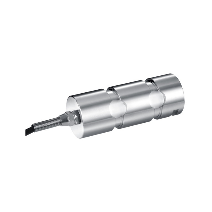
METRAVON MV-LC0145 is a double-shear load pin for measuring radial reaction within a sheave or other mechanical joint. The nominal range is 1-40 t, with pin diameter and length changing by rated group. Replacing an ordinary shaft introduces a measurement condition as well as a mechanical connection: the supporting members, loaded region and orientation must correspond to the rated sensor arrangement. Submit the joint section and force directions before selecting a replacement.
Define the radial load pin reaction at the sheave
The force carried by a sheave pin depends on the directions of the rope legs and the mechanism layout. It is not automatically equal to one rope tension or to the payload. Provide the operating positions, rope path and maximum expected pin reaction. Include the loaded member, outer supports, bushes and clearances on a section through the joint. The sensing pin must be assessed with those contacts; a nominal shaft diameter match alone does not establish the calibration condition or structural suitability.
Use the correct rated geometry rather than one family photograph
The 1-5 t group shows diameter A=40 mm and L=120 mm. The 8-10 t group changes to 55/160 mm, the 15-20 t group to 65/200 mm and the 30-40 t group to 85/250 mm. Local C, D and E dimensions also change, affecting where force is introduced relative to the relieved sections. Have the complete toleranced rated drawing approved for the actual bearing arrangement. Do not interpolate a missing capacity or place a bush wherever the overall pin length permits.
| Item | Value | Selection notes |
|---|---|---|
| 1-5 t: diameter A / L | 40 / 120 mm | C=15, D=15, E=25 mm; confirm the complete bearing section. |
| 8-10 t: diameter A / L | 55 / 160 mm | C=20, D=22, E=40 mm; do not retain a smaller joint by assumption. |
| 15-20 t: diameter A / L | 65 / 200 mm | C=25, D=27, E=50 mm; use the selected rated outline. |
| 30-40 t: diameter A / L | 85 / 250 mm | C=30, D=32, E=80 mm; review supporting steelwork separately. |
| Bridge reference / excitation | 1.0-1.5 mV/V / 5-12 V | Obtain the actual calibration value and delivered cable schedule. |
| Operating interval / protection | -20 to +70 deg C / IP66 | Confirm material and the completed cable installation. |
Specify the signal version before choosing the receiving input
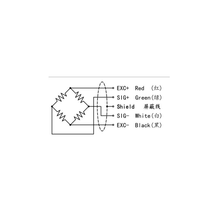
The bridge sensitivity reference is 1.0-1.5 mV/V and requires a supplied calibration value for the actual rated version. Bridge excitation is 5-12 V, with 750 +/-30 ohms input and 700 +/-5 ohms output resistance. An internal transmitter is mentioned as an option for current or voltage signals, but the general description does not define one universal range, supply or wiring scheme for those options. Identify the delivered interface, scaling and cable functions in the quotation before selecting the PLC input or applying power.
Compare the working interval with separate error entries
The non-linearity reference spans +/-0.1 to +/-0.3% FS; the applicable figure must be confirmed for the offered pin. Hysteresis and repeatability are separately listed at +/-0.1% FS. They are not one guaranteed installed accuracy or interchangeable definitions. Specify the useful reaction interval and the temperatures at the pin so that the complete measurement can be assessed. Zero and sensitivity temperature coefficients are each listed as +/-0.05% FS per 10 deg C, not a correction automatically supplied by the controller.
Accept the assembled joint and document the replacement
Use agreed independent reactions through the final supports, comparing repeat readings and the return after unloading. Record pin orientation, retention, bushes, selected interface and reader scaling. Check alloy steel or stainless steel and the IP66 cable arrangement against actual exposure; the operating interval is -20 to +70 deg C. The sensor 150% FS safe-overload reference does not approve a proof load for the sheave, bracket or lifting equipment. Any protective monitoring function requires its own documented system assessment.
Sheave reaction, transmitter options and bearing fit
Q1. Does a 10 t pin mean the displayed rope tension is always 10 t at full scale?
The pin measures joint reaction. Its relationship to rope tension depends on the rope directions and sheave geometry. Define that conversion and verify it with the actual mechanism before assigning the displayed quantity.
Q2. Can an internal transmitter be ordered simply as a universal 4-20 mA version?
The option description does not establish that exact range or supply for every configuration. State the required current or voltage input and obtain a confirmed output, power, scaling and terminal schedule for the offered version.
Q3. Can the 1-5 t group be used with any 40 mm bush?
The nominal diameter does not settle fit, contact widths, support positions or orientation. Compare the controlled pin drawing with the complete joint and confirm the rated reaction arrangement.
