


 Chinese
 Spanish
 Russian
 Portuguese
 French
 German
 Indonesian
 Thai
 Vietnamese
 Arabic
 Italian
 Turkish
 Polish
 Japanese



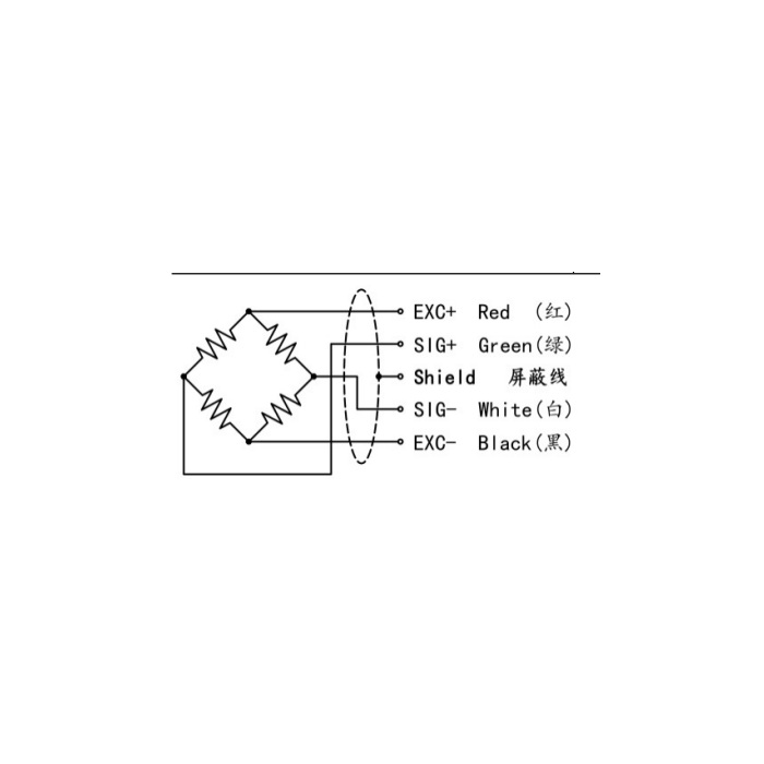
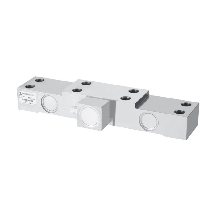
METRAVON MV-LC0144 is a pillow block load cell using a double-shear-beam structure, documented for fixed-sheave bases and load monitoring in lifting and water-related equipment. The family range is 1.5-20 t. It measures the force transferred through its support arrangement; converting that result into rope tension requires the actual rope and sheave geometry, not just a display-unit change.
Determine what the pillow block load cell reaction represents
A sheave support carries the resultant of the forces from the rope sections as well as relevant assembly weight. Rope directions, contact geometry and friction can affect the relationship between support reaction and the required tension value. Provide a force-path sketch with the intended rope positions before selecting capacity or setting a conversion factor. A calibration performed with a downward reference load verifies that loading condition, not every possible rope angle in service.
Match the bearing attachment and outer base patterns separately
The 1.5 t dimensional row gives a 350 mm body length L, 75 mm width W and 100 mm central attachment spacing L2. At 2.5 t, L/W/L2 become 410/100/130 mm. The 4-10 t row retains 410 mm length and 100 mm width but increases L2 to 160 mm. Compare the complete central bearing pattern, outer foundation pattern and counterbores; matching body length alone can leave the bearing unsupported or the holes misaligned.
| Item | Value | Selection notes |
|---|---|---|
| Family range | 1.5-20 t | Select against the greatest relevant support reaction. |
| 1.5 t L / W / L2 | 350 / 75 / 100 mm | Check both central and outer fixing patterns. |
| 2.5 t L / W / L2 | 410 / 100 / 130 mm | A shared length with another row does not establish a match. |
| 4-10 t L / W / L2 | 410 / 100 / 160 mm | The central attachment spacing changes. |
| 15-20 t L / W | 520 / 145 mm | Obtain the full bearing and foundation drawing. |
| Working temperature | -20 to +70 deg C | Confirm the environment of the installed support and cable. |
Review the foundation and final bridge connection
The 15-20 t row changes to 520 mm length and 145 mm width with a different fixing arrangement. Confirm the selected rating, bearing, base stiffness and fastening instructions as a complete support. The alloy-steel sensor has IP66 listed, a 3 m cable of 5 mm diameter and a 5-12 V DC excitation range. Input resistance is 750 +/-30 ohms and output resistance 700 +/-5 ohms. Obtain actual rated sensitivity from the listed 1.0-1.5 mV/V entry before setting channel gain.
Validate indication and any alarm through the complete measurement chain
Use agreed reference loading and the relevant rope configurations to check zero, scaling and repeat response. Nonlinearity is listed as +/-0.1-0.3% FS; this is not a promise of complete tension-system accuracy. Where a controller uses the signal for an alarm, verify the full signal path and separately assess the required protective function. The 150% safe-overload entry is neither an alarm setpoint nor evidence that the sensor alone is a certified overload-protection system.
Rope tension, bearing fit and alarm limits
Q1. Is the support-force reading equal to rope tension?
Not without a valid relationship for the actual rope directions, sheave and assembly. Review the forces and reference method with the system designer. The support reading cannot be relabelled as tension solely by entering a capacity number into the display.
Q2. Can the 2.5 t bearing bracket be reused for the 4-10 t group?
The body length and width match, but central attachment spacing L2 changes from 130 to 160 mm. Compare the full bearing pattern, counterbores and outer foundation connections. Do not approve the bracket from the envelope dimensions alone.
Q3. Can the 150% overload figure be entered as the trip threshold?
It is not a recommended operating or alarm limit. Set the required protection behaviour from the equipment limits and a separate system assessment, then verify the full controller and signal chain. The sensor capacity and overload entry do not define a safe lifting-system trip setting.
