


 Chinese
 Spanish
 Russian
 Portuguese
 French
 German
 Indonesian
 Thai
 Vietnamese
 Arabic
 Italian
 Turkish
 Polish
 Japanese



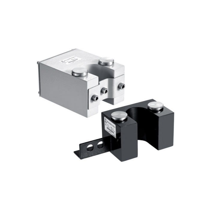
METRAVON MV-LC0143 is a side-entry oilfield load cell with a twin-column measuring arrangement for pumpjack systems. The family is listed at 10-20 t. The open-side geometry changes installation access, but does not remove the need to review the load contacts, central-member clearance and the site procedure for supporting the load before installation or removal.
Review side-entry oilfield load cell clearance and contact seating
The reference drawing includes a 41 mm slot-width callout and a 49 mm circular-clearance detail. Compare both features with the central member and the full load stack; do not treat them as interchangeable bore diameters. Check how the upper and lower parts seat on the measuring contacts, and identify the bracket configuration in the offered drawing. A twin-column arrangement does not establish an unlimited tolerance for eccentric loading or contact on only one side.
Separate access geometry from a safe installation method
Side access is not permission to insert or remove the sensor under a supported operating load. The site must use its approved isolation and independent load-support procedure with qualified personnel. Provide the available access, adjacent clamps and required maintenance clearance for review. After installation, inspect the final seating and unloaded reference condition, then verify known or agreed reference loads before the recorded operating signal is accepted.
Name the delivered signal package on the order
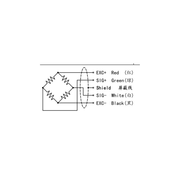
The sensor specification gives 1.0-1.5 mV/V sensitivity with +/-0.05 mV/V tolerance, a 750 +/-30 ohm input and 700 +/-5 ohm output. Excitation is 5-12 V DC and a 3 m cable is listed. Current, voltage or wireless transmission requires a confirmed conditioning or transmission arrangement; no particular output range, radio protocol or power system is established by the bridge specification. Identify each component and its data connection to the RTU or logger.
| Item | Value | Selection notes |
|---|---|---|
| Family rating | 10-20 t | Request the offered rated version and assembly drawing. |
| Slot / circular detail | 41 / 49 mm | Check each feature against the intended central-member clearance. |
| Nominal output entry | 1.0-1.5 mV/V | Confirm actual sensitivity and its listed tolerance. |
| Excitation / cable | 5-12 V DC / 3 m | The specified lead has a 5 mm diameter. |
| Working temperature | -20 to +70 deg C | Assess the sensor location and any transmitter separately. |
| Material / protection | Steel options / IP66 | Confirm material and applicable site approval requirements. |
Check the force record through a representative cycle
Agree the operating force range, required recording interval and any stroke-position reference. Confirm zero, reference-load scaling and the behaviour of the complete channel after the final seating and cable route are established. Repeatability is listed as +/-0.2% FS and creep as +/-0.1% FS, without a stated creep duration. Nonlinearity is +/-0.3-0.5% FS. Use the offered performance and agreed verification method rather than describing these separate entries as a single system-accuracy guarantee.
Side access and the complete signal package
Q1. Does side entry mean the sensor can be fitted while the pumpjack remains loaded?
No such installation permission follows from the shape. Establish isolation, independent load support and the approved site method before touching the load stack. The accepted installation also needs correctly seated contacts and a verified reference condition.
Q2. Is wireless transmission included with the bridge sensor?
The bridge table does not define a complete wireless package. Obtain the transmitter, power arrangement, receiver or gateway, communications details and enclosure scope on the offer. Verify how the final load value reaches the actual RTU or recording system.
Q3. Can the open slot compensate for an offset load automatically?
The twin-column construction is not a quantified allowance for arbitrary offset. Provide the contact positions and likely eccentricity, then obtain the applicable limits for the proposed assembly. Confirm seating and channel response under the required operating conditions.
