


 Chinese
 Spanish
 Russian
 Portuguese
 French
 German
 Indonesian
 Thai
 Vietnamese
 Arabic
 Italian
 Turkish
 Polish
 Japanese



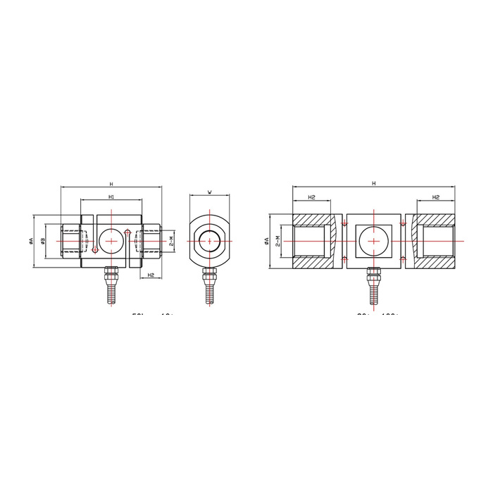
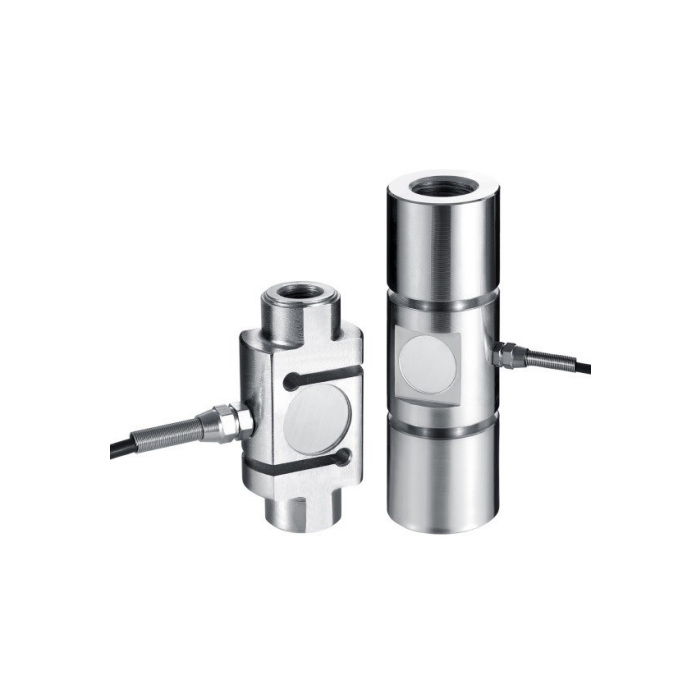
METRAVON MV-LC0140 is a column tension and compression load cell with internally threaded end connections for industrial force-testing and weighing assemblies. The documented family extends from 50 kg to 100 t, with different body forms and end threads across the dimensional groups. Specify the actual rated version, mating attachments and required tensile and compressive loads together.
Match the column tension and compression load cell to both attachments
The 50-700 kg reference group has an 88 mm end-to-end dimension H and M16 x 1.5 threads; 1-5 t changes to 112 mm and M24 x 1.5. The 8-10 t group uses 160 mm and M36 x 4. Higher rows include 30 t at 213 mm with M45 x 4.5 and 100 t at 367 mm with M76 x 3. These are not a common body with different electronic scaling. Check thread engagement, attachment alignment and the complete installation length before approving a fixture.
| Item | Value | Selection notes |
|---|---|---|
| Family range | 50 kg-100 t | Obtain a confirmed rating and its dimensional row. |
| 50-700 kg H / thread | 88 mm / M16 x 1.5 | Review the internally threaded mating connection. |
| 1-5 t H / thread | 112 mm / M24 x 1.5 | Attachment size and overall assembly length increase. |
| 8-10 t H / thread | 160 mm / M36 x 4 | Check the adjoining structure for the actual force cycle. |
| 30 t H / thread | 213 mm / M45 x 4.5 | This is not the same envelope as a stud-end alternative. |
| Excitation / cable | 5-12 V DC / 3 m | Confirm the reader and delivered cable termination. |
Verify tension and compression separately in the final force path
Keep the adjoining load members aligned and identify any side load, bending or reversal in the machine cycle. A threaded connection does not eliminate bending introduced by an offset fixture. After the attachments are secured, establish zero and apply suitable reference forces in each required direction. Record signal sign, repeat readings and return to zero. A correct tensile span does not demonstrate the compressive response of the assembled test fixture.
Use the stated bridge supply and actual rated output
Sensitivity is 2.0 +/-0.05 mV/V, with 380 +/-30 ohms input resistance and 350 +/-5 ohms output resistance. The excitation range is 5-12 V DC, not a direct 24 V industrial supply. A 3 m cable of 5 mm diameter is listed. Confirm the delivered termination and reader input, then set the channel scale with the actual sensor. If a PLC requires a conditioned signal, identify the amplifier and control-system interface separately.
Set acceptance limits without combining unrelated error entries
Nonlinearity and hysteresis are each listed in the +/-0.05-0.1% FS range, while repeatability and creep are each +/-0.05% FS. Confirm the offered performance and the observation period used for creep; no duration is stated in this entry. Do not present the smallest individual figure as complete fixture accuracy. Working temperature is -20 to +70 deg C. The IP65/IP66 entries and material choice need confirmation for the ordered construction and its completed electrical connection.
For an external-stud connection, review MV-LC0141 separately; its end threads, body lengths and electrical options differ.
End connections and cyclic force limits
Q1. Can a stud-ended sensor replace this part if the thread diameter matches?
The internal connection shown here and an external stud require different mating parts. Compare thread pitch, engagement, overall length and the adjoining attachments. Any adapter becomes part of the force fixture and needs its own mechanical review and calibration check.
Q2. Does a 150% safe-overload entry permit repeated operation above the rating?
It is not an enlarged measurement range or a fatigue-life statement. Define the normal peaks, reversals and any abnormal loads before selecting the rating. Resolve overload protection at machine level rather than treating the safe-overload value as a working target.
