


 Chinese
 Spanish
 Russian
 Portuguese
 French
 German
 Indonesian
 Thai
 Vietnamese
 Arabic
 Italian
 Turkish
 Polish
 Japanese



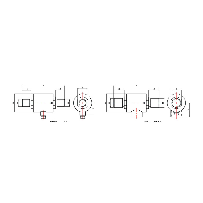
METRAVON MV-LC0141 is a stud-end tension and compression load cell for axial force-testing and weighing equipment. The documented family covers 500 kg to 300 t. External threaded attachments and body dimensions vary with capacity, while the sensitivity and resistance entries also require confirmation for the offered version. A model-family name alone is not enough to specify a replacement.
Resolve the electrical version before reusing an amplifier
Specified sensitivity is 1.5-2.0 mV/V with a listed tolerance of +/-0.05 mV/V; obtain the actual rated output and calibration data. The input resistance can be 380 +/-30 or 750 +/-30 ohms, while the output resistance can be 350 +/-5 or 700 +/-5 ohms. Confirm the supplied combination rather than independently choosing values or assigning them to a capacity. The reader must support the delivered bridge and its excitation demand before its span can be recalibrated.
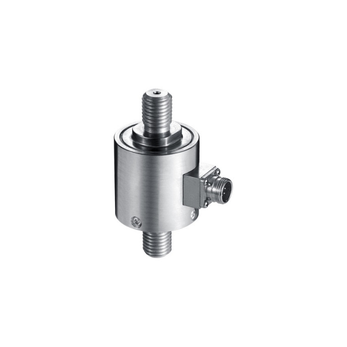
The stud-end tension and compression load cell changes length and pitch
At 500 kg-2 t the reference diameter is 45 mm, overall length L is 95 mm and the end thread is M16 x 2. At 3-5 t these become 60 mm, 140 mm and M24 x 3; 8-10 t keeps a 60 mm diameter but changes to 150 mm and M30 x 3.5. Compare the full row and mating couplings. Equal body diameter does not establish equal installed length or a reusable thread.
| Item | Value | Selection notes |
|---|---|---|
| 500 kg-2 t diameter / L | 45 / 95 mm | The external end thread is M16 x 2. |
| 3-5 t diameter / L | 60 / 140 mm | Use the M24 x 3 coupling specification. |
| 8-10 t diameter / L | 60 / 150 mm | The end thread changes to M30 x 3.5. |
| 30 t / 50 t length L | 240 / 270 mm | The shared diameter does not give a common thread. |
| 300 t diameter / L | 185 / 500 mm | Review the M130 x 6 attachment and complete load frame. |
| Temperature / protection | -20 to +70 deg C / IP65 | Confirm conditions at the sensor and completed connection. |
Reserve installation space for the higher-capacity versions
The 30 t row gives 94 mm diameter, 240 mm length and M45 x 4.5; 50 t retains the 94 mm diameter but uses 270 mm and M64 x 3. The 300 t reference reaches 185 mm diameter and 500 mm length with M130 x 6. Include attachment lengths, tightening access, cable or connector clearance and the capacity of adjoining members. Do not infer the acceptance of a larger load from a sensor change alone.
Verify the complete bidirectional channel after assembly
Use suitable bridge electronics within the specified 5-12 V DC excitation range. A 3 m, 5 mm diameter cable entry is listed; confirm termination and connector scope with the offer. Apply agreed references in tension and compression, recording zero, sign, repeat behaviour and return. Nonlinearity is listed as +/-0.05-0.1% FS, not a complete test-machine error limit. Agree any hold test separately because the +/-0.05% FS creep entry does not specify an observation duration.
Electrical variants and retained couplings
Q1. Can the 750 ohm entry be assumed for every high-capacity order?
The specification does not map the electrical entries to individual capacities. Obtain input resistance, output resistance and actual sensitivity for the offered unit. Use those data to assess the reader, particularly when channels share an excitation supply.
Q2. Does the 3 m cable entry mean the pictured connector is included?
A cable length does not establish connector type, pinout or scope of supply. Confirm the delivered termination, mating plug and cable assembly in the quotation. Retain the documented wiring with the channel calibration record.
Q3. Can the 3-5 t couplings be retained for a 10 t sensor because both bodies are 60 mm wide?
The 8-10 t row has a different length and M30 x 3.5 thread rather than M24 x 3. Compare both couplings and the entire force frame before accepting the change. The shared body diameter is only one clearance dimension.
