


 Chinese
 Spanish
 Russian
 Portuguese
 French
 German
 Indonesian
 Thai
 Vietnamese
 Arabic
 Italian
 Turkish
 Polish
 Japanese



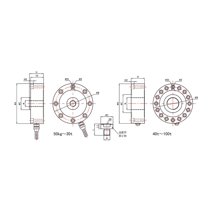
METRAVON MV-LC0139 is a spoke-type load cell using a shear-stress measuring structure for hopper weighing and industrial force fixtures. The listed family extends from 50 kg to 500 t, but the dimensional rows cover configurations only through 100 t. Select the actual rated build and obtain its centre attachment and flange drawing before committing to a support design.
Match the spoke-type load cell centre and flange as one interface
The 50-700 kg row gives 88 mm outside diameter, 72 mm fixing circle, 34 mm height H and an M12 x 1.75 centre connection with eight 7 mm fixing holes. At 1-5 t the outside diameter is 105 mm, height 37 mm and centre thread M16 x 1.5. The 10-20 t row changes to 120.6 mm diameter, 53.5 mm height and M32 x 1.5. The centre attachment and the peripheral support must suit the same selected row.
Check the fixing-count change and the limit of the available drawings
The 30 t row retains eight fixings, while the 40-60 t row changes to sixteen 13 mm holes on a 174 mm fixing circle and a 208 mm outer diameter. The 80-100 t group uses sixteen 17 mm holes, a 230 mm fixing circle and a 280 mm outer diameter. Do not extend those dimensions to ratings above 100 t. Obtain a confirmed installation drawing for any higher-rated offer instead of scaling a smaller flange or assuming the same bolt pattern.
| Item | Value | Selection notes |
|---|---|---|
| Listed family range | 50 kg-500 t | Confirm exact rated availability and the matching build. |
| Available dimensional coverage | Through 100 t | Require the selected drawing above that coverage. |
| 50-700 kg fixing pattern | Eight 7 mm holes | The fixing circle is 72 mm; review counterbores separately. |
| 40-60 t fixing pattern | Sixteen 13 mm holes | Use the 174 mm circle and matching centre attachment. |
| 80-100 t fixing pattern | Sixteen 17 mm holes | The fixing circle increases to 230 mm. |
| Working temperature | -20 to +70 deg C | Confirm the material and IP65/IP66 construction. |
Identify the actual bridge before selecting shared excitation
Rated sensitivity is 2.0 +/-0.05 mV/V. The input-resistance alternatives are 750 +/-30 or 1450 +/-30 ohms, and the output alternatives are 700 +/-5 or 1400 +/-5 ohms. Confirm the delivered combination and its calibration data; the capacity label does not assign these electrical values. Check the complete load on any shared excitation supply. The specified bridge supply is 5-12 V DC and a 3 m cable of 5 mm diameter is listed.
Verify the flange assembly, not just the loose sensing element
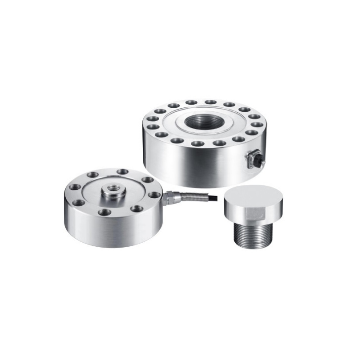
Provide the central load direction, mating contact, base stiffness and fastening arrangement. The loading button shown as an accessory does not establish inclusion in the sensor price or a universal contact profile. After the complete fixture is secured, apply reference loads and inspect repeat readings, unload return and any required held-load condition. Nonlinearity is +/-0.05-0.1% FS; the separate +/-0.05% FS hysteresis, repeatability and creep entries are not a blanket accuracy guarantee for the assembled hopper.
High-capacity drawings and contact scope
Q1. Does the 500 t family limit mean the 100 t mounting can be enlarged proportionally?
The published dimensional rows do not establish that geometry. Obtain the offered high-capacity sensor drawing, fastening requirements and centre interface. The adjoining structure and reference-loading method need their own review at the proposed load.
Q2. Is a higher-resistance version automatically assigned to the largest ratings?
No capacity-to-resistance assignment is given. Confirm actual input resistance, output resistance and rated sensitivity on the offer or unit documentation. Size the excitation supply for the connected configuration rather than a guessed bridge value.
Q3. Is the pictured loading button part of every delivery?
Treat the contact piece as a separate scope item until confirmed. Identify its thread, contact profile and dimensions with the selected sensor drawing. A photograph alone does not establish inclusion or suitability for every flange size.
