


 Chinese
 Spanish
 Russian
 Portuguese
 French
 German
 Indonesian
 Thai
 Vietnamese
 Arabic
 Italian
 Turkish
 Polish
 Japanese



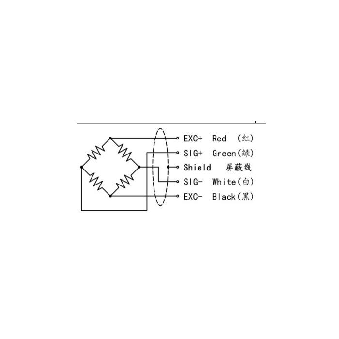
METRAVON MV-LC0136 is a miniature S-type load cell for space-limited assembly-force, button-feel and robotic gripping fixtures. The stainless-steel family is listed at 5-50 kg with M4 loading attachments. Check the required force interval as well as the installation space: a small body does not establish that the complete channel can resolve every small force change in an assembly process.
Install the miniature S-type load cell without bypassing its flexure
The drawing shows a 16 mm width, 19.1 mm height and 6 mm thickness. Both loading ends are marked M4, without a specified pitch or engagement length. Obtain the mating details and fastening instructions before making the fixture. Keep neighbouring components clear of the slotted measuring section and support the cable independently. A bracket that touches another part of the body can create a second force path, even when the sensor fits within the available space.
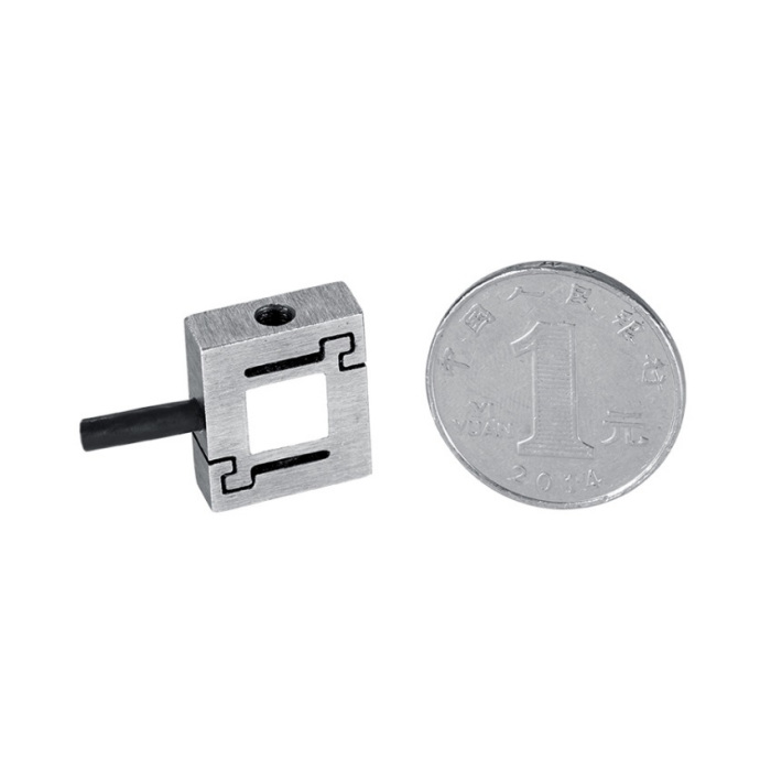
Use individual calibration rather than assuming exactly 2 mV/V
The nominal rated sensitivity is 2.0 mV/V with a +/-10% tolerance. This describes variation in the rated signal between units, not a claim that a calibrated force reading has a 10% error. Confirm actual sensitivity and scale the measuring channel from reference loads. Input and output resistances are each 350 +/-5 ohms, with 5-12 V DC excitation. The listed lead is 3 m long and 3 mm in diameter; route it in its final position before evaluating the small-force response.
Specify the minimum useful force and cycle timing
Provide the maximum axial force, preload, required small-force change and machine cycle. If the result is a force-versus-travel curve, identify the displacement reference and acquisition timing. The sensor table does not specify a dynamic bandwidth, sampling rate or complete force-resolution figure. Verify those requirements with the actual amplifier, acquisition system and mounted tooling instead of inferring them from the miniature size or nominal bridge output.
| Item | Value | Selection notes |
|---|---|---|
| Family range | 5-50 kg | Confirm the offered rating and required measurement interval. |
| Width / height / thickness | 16 / 19.1 / 6 mm | Add attachment and cable-bend clearances. |
| Loading designation | M4 at both ends | Obtain pitch, engagement and the approved fastening method. |
| Bridge input / output | 350 +/-5 / 350 +/-5 ohms | Check reader gain using the actual calibrated sensitivity. |
| Lead length / diameter | 3 m / 3 mm | Do not copy the thicker cable of an adjacent S-type model. |
| Temperature / protection | -20 to +70 deg C / IP66 | Assess conditions at the mounted sensor and connection. |
Review overload and return behaviour on the assembled tool
The design includes overload-protection geometry and lists a 150% FS safe-overload value, but no permissible impact energy, stop travel or cycle-life rating is stated. Define foreseeable force peaks rather than treating the internal stops as permission for repeated collisions. Nonlinearity, hysteresis, repeatability and creep are each listed as +/-0.1% FS, with no creep duration given. Confirm return and repeat readings through the intended tensile or compressive operating cycle.
Sensitivity tolerance and machine-force limits
Q1. Does the +/-10% sensitivity tolerance mean a 10% force error?
It applies to nominal rated output. A suitable reader can be calibrated for the actual unit, while the sensor error characteristics and fixture still determine the installed result. Set an acceptance requirement for the useful force interval and verify it with references.
Q2. Do the internal stops make a press collision harmless?
No impact-energy or repeated-collision allowance is provided. Review the machine force limits, external stops and abnormal loads separately. Inspect the channel after a suspected overload instead of relying on a plausible zero reading.
Q3. Can the smallest button force be selected from the body size?
Body dimensions answer a fit question, not a resolution question. Define the smallest useful change and check noise, gain, reference loading and tooling effects on the actual channel. Confirm suitability before adopting it for a force curve or pass/fail threshold.
