


 Chinese
 Spanish
 Russian
 Portuguese
 French
 German
 Indonesian
 Thai
 Vietnamese
 Arabic
 Italian
 Turkish
 Polish
 Japanese



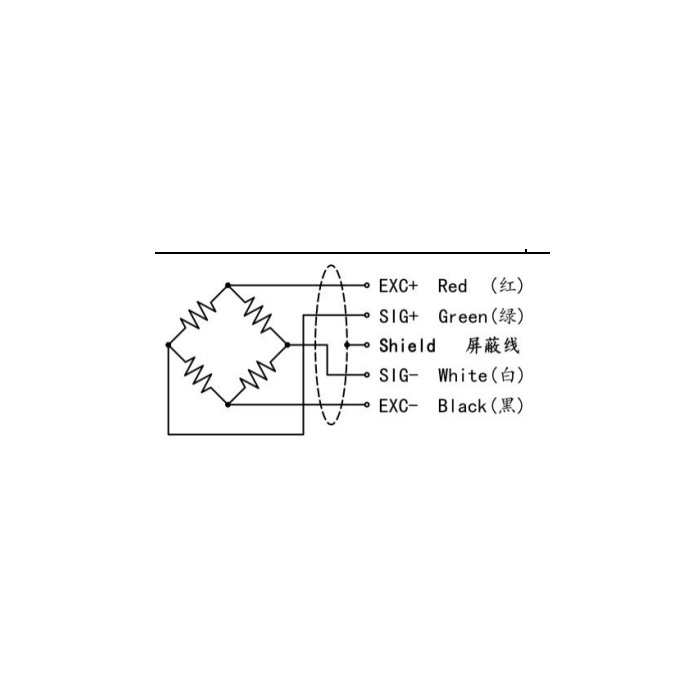
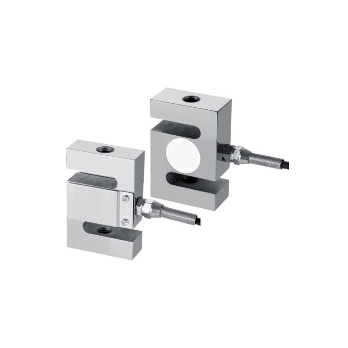
METRAVON MV-LC0135 is an S-type tension and compression load cell for industrial force-testing and weighing fixtures. The documented family covers 5 kg to 5 t. Its four dimensional groups change thread, height and thickness, so specifying a capacity without the matching drawing can leave the attachment and available space unresolved.
Fit the S-type tension and compression load cell by its full envelope
The 5-50 kg row gives length L = 50.8 mm, height H = 63.5 mm and body thickness W = 12.7 mm, with M8 x 1.25 attachments. At 100-300 kg, L remains 50.8 mm but H increases to 76.2 mm and W to 19 mm, with M12 x 1.75. The 500 kg-1 t group keeps that length, height and thread but increases thickness to 25.4 mm. A height-only check misses this clearance difference.
| Item | Value | Selection notes |
|---|---|---|
| 5-50 kg L / H / W | 50.8 / 63.5 / 12.7 mm | The specified attachment is M8 x 1.25. |
| 100-300 kg L / H / W | 50.8 / 76.2 / 19 mm | Use the M12 x 1.75 version drawing. |
| 500 kg-1 t L / H / W | 50.8 / 76.2 / 25.4 mm | Greater thickness matters despite the shared height. |
| 2-5 t L / H / W | 76.2 / 108 / 25.4 mm | Both attachments change to M18 x 1.5. |
| Nonlinearity | +/-0.03-0.05% FS | Confirm the offered value; it is not the whole fixture error. |
| Cable | 3 m; 5 mm diameter | Reserve room for the gland and protected route. |
| Excitation | 5-12 V DC | No direct 24 V field connection is specified. |
Review the end fittings and mounting access at 2-5 t
The 2-5 t row changes to L = 76.2 mm, H = 108 mm, W = 25.4 mm and M18 x 1.5 threads. Include the couplings, locking arrangement and cable access when calculating the installed span. The fixture must introduce force along the intended axis without bending from offset attachments. Resolve any articulation or alignment requirement from the complete fixture, rather than assuming an S-shaped body tolerates arbitrary side loading.
Calibrate the bidirectional channel with the installed attachments
Rated sensitivity is 2.0 +/-0.05 mV/V, with 380 +/-30 ohms input and 350 +/-5 ohms output resistance. Use a bridge reader with 5-12 V DC excitation and confirm the delivered termination of the listed 3 m cable. Establish unloaded zero after the attachments are secure, then verify the reference forces required in tension and compression. Keep the sign convention consistent at the display or control input; a tensile check alone does not validate the reverse direction.
Include a held-force check when the process dwells
A fixture that maintains a constant pull needs an agreed dwell test, not only an immediate span reading. Record the indication during the hold and after release. Creep is specified as +/-0.03% FS without a time interval, so obtain the applicable conditions before deciding the observation duration. For repeated clamp-and-release duty, compare the loading and unloading paths as well: hysteresis and repeatability are each +/-0.03% FS. Check the sensor temperature near any heated tooling against the -20 to +70 deg C range.
Shared height and attachment alignment
Q1. Can a 500 kg unit use a fixture designed for the 100-300 kg body?
Length, height and thread match in the table, but thickness increases from 19 to 25.4 mm. Check the fixture opening, coupling clearance and cable exit. Approve the complete revised arrangement before assuming the higher rating fits.
Q2. Will an unloaded zero adjustment remove errors from an offset attachment?
Zeroing removes the current indicated offset, not the mechanical cause of a changing bending force. Review alignment and contact throughout the loading cycle. Test reference forces after the fixture has been corrected and the final attachments are secured.
