


 Chinese
 Spanish
 Russian
 Portuguese
 French
 German
 Indonesian
 Thai
 Vietnamese
 Arabic
 Italian
 Turkish
 Polish
 Japanese



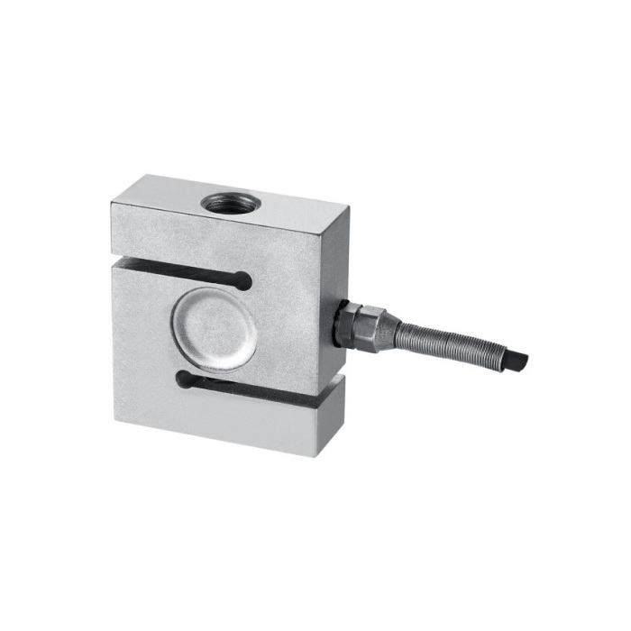
METRAVON MV-LC0134 is an S-type tension and compression load cell for industrial force measurement and weighing fixtures in the 1-5 t family. Its three dimensional rows separate 1 t, 2 t and 3-5 t bodies. Review both threaded attachments and the surrounding fixture clearance rather than assuming every version shares a common envelope.
Check the S-type tension and compression load cell dimensions at each rating
The 1 t row gives L = 60 mm, H = 70 mm and thickness W = 25 mm, with M16 x 2 attachments. At 2 t, H, W and the thread remain unchanged but L increases to 64 mm. The 3-5 t group increases to L = 86 mm, H = 94 mm, W = 35 mm and M18 x 1.5. Use the dimension letters with the drawing: L is not a substitute for the complete installed span between the external fittings.
Keep fitting loads on the intended axis
Describe tension, compression, preload and any reversal in the force cycle. Check end-thread pitch, engagement and locking with the mating parts, and include coupling length and cable-gland clearance in the installation review. An S-shaped measuring body does not correct bending introduced by offset couplings. If the machine needs articulation, specify the attachment arrangement and verify that it remains clear during the operating movement instead of forcing a rigid connection into position.
| Item | Value | Selection notes |
|---|---|---|
| 1 t L / H / W | 60 / 70 / 25 mm | Both loading connections are M16 x 2. |
| 2 t L / H / W | 64 / 70 / 25 mm | Check side clearance despite unchanged height and thread. |
| 3-5 t L / H / W | 86 / 94 / 35 mm | Use the M18 x 1.5 attachment drawing. |
| Rated bridge sensitivity | 2.0 +/-0.05 mV/V | Calibrate the actual installed measuring channel. |
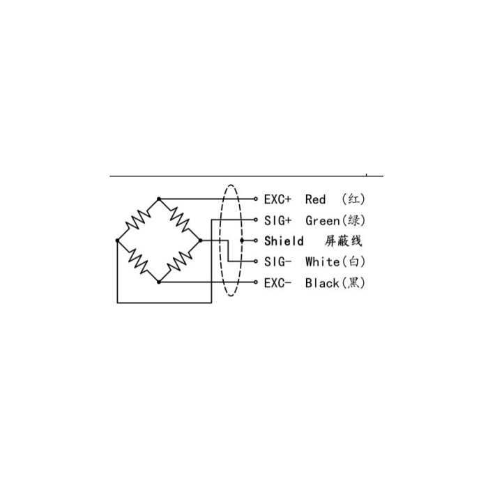
| Excitation / cable | 5-12 V DC / 3 m | Select compatible bridge electronics and verify the final wiring. |
| Safe-overload entry | 150% FS | This is not an extended working range or a fatigue-life rating. |
Verify reader scaling through the final load members
The bridge gives 2.0 +/-0.05 mV/V, with 380 +/-30 ohms input resistance and 350 +/-5 ohms output resistance. It requires 5-12 V DC excitation, and the cable entry is 3 m at 5 mm diameter. Complete assembly before establishing zero and reference span. Check the actual force indication in both required directions and record sign and return after release; a positive reading on a bench indicator does not verify the negative-force channel in the final machine.
Use process-specific reference points instead of a nominal accuracy label
Agree the force interval used for pass/fail decisions, repeat tests around those points and examine loading versus unloading readings. Nonlinearity is listed as +/-0.03-0.05% FS and hysteresis as +/-0.03% FS. These values do not remove the influence of attachments or the reader. For dwell processes, obtain conditions for the +/-0.03% FS creep entry rather than attaching an unstated test duration. Working temperature is -20 to +70 deg C, with IP66 housing protection listed.
Body clearance and force reversal
Q1. Will a 2 t body fit a fixture made for 1 t?
The table keeps the 70 mm height, 25 mm thickness and M16 x 2 threads, but L increases by 4 mm. Compare the side opening, gland access and adjoining members before approving the replacement. Any higher working load still needs assessment of the complete fixture.
Q2. Can an M16 coupling be retained for the 3-5 t group?
That group uses M18 x 1.5, with a larger body and height. Do not force or adapt the connection merely because the measuring principle is the same. Approve the complete mating hardware, installed span and working load before calibration.
Q3. Does zeroing compensate for coupling strain during a reversal?
A zero setting removes an indicated offset at one condition; it does not correct a force path that changes as the fixture reverses. Inspect coupling movement and bending, then check suitable tensile and compressive references after the mechanical issue is resolved.
