


 Chinese
 Spanish
 Russian
 Portuguese
 French
 German
 Indonesian
 Thai
 Vietnamese
 Arabic
 Italian
 Turkish
 Polish
 Japanese



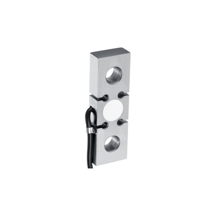
METRAVON MV-LC0133 is a compact plate-ring tension load cell with separate 1, 2 and 3 t dimensional rows. It is intended for tensile load measurement in hook-scale and related industrial assemblies. Its short body can be useful where connected length is limited, but the pin spacing and hole size change with each listed rating.
Choose the compact plate-ring tension load cell from its pin pattern
At 1 t the overall length is 105 mm, pin centres 70 mm, plate height 35 mm and thickness 16 mm, with 15 mm end holes. The 2 t version changes to 130 mm length, 85 mm centres, 40 mm height and 20 mm thickness with 20 mm holes. At 3 t the length is 150 mm, centres 95 mm and height 45 mm; thickness stays 20 mm while holes increase to 25 mm. No single mounting pattern covers all three versions.
| Item | Value | Selection notes |
|---|---|---|
| 1 t L / centres / holes | 105 / 70 / 15 mm | Plate height and thickness are 35 and 16 mm. |
| 2 t L / centres / holes | 130 / 85 / 20 mm | Plate height and thickness are 40 and 20 mm. |
| 3 t L / centres / holes | 150 / 95 / 25 mm | Height rises to 45 mm while thickness remains 20 mm. |
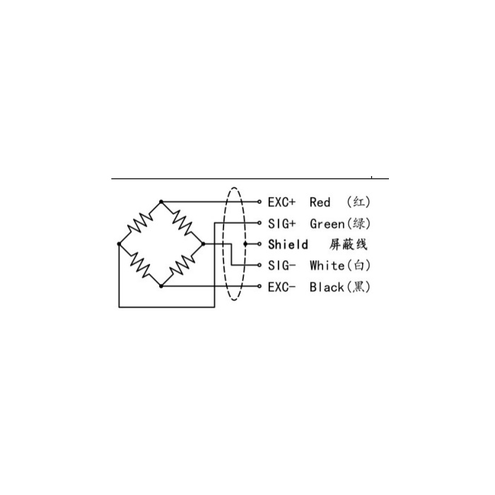
| Excitation / cable | 5-12 V DC / 3 m | Confirm the delivered wiring and external reader. |
| Nonlinearity | +/-0.05-0.1% FS | Use the confirmed offered value in the measurement assessment. |
| Working temperature | -20 to +70 deg C | Review IP66 field-connection protection at the actual location. |
Check connected length and side clearance before ordering the link
Add the mating attachment dimensions to the sensor pin-centre distance when reviewing the full installation. Inspect clevis opening, pin retention, movement and cable exit around the actual assembly. A matching hole diameter alone does not establish pin fit or the capacity of the attached hardware. Keep force in the intended tensile path and obtain confirmation before introducing an offset, twist or a load reversal that the proposed arrangement has not been assessed for.
Keep the bridge version and display scaling together
The sensitivity specification lists 1.5-2.0 mV/V with a +/-0.05 mV/V tolerance. Confirm actual rated output and the selected sensor capacity before configuring a reader. At 10 V excitation, the two nominal sensitivity endpoints correspond to 15 and 20 mV, so an old gain or span should not be copied without review. The bridge input is 380 +/-30 ohms and output 350 +/-5 ohms; the excitation requirement is 5-12 V DC.
Inspect the final pin assembly during reference loading
A 3 m cable of 5 mm diameter is listed. Complete its protected routing, establish the initial indication and apply reference tension through the intended pins. Repeat selected loads and check the indication after release; record any attachment movement or rubbing observed during the test. The +/-0.05% FS hysteresis, repeatability and creep entries do not specify a full lifting-system accuracy or a creep duration. Define the required acceptance conditions and any protective function separately.
MV-LC0132 provides another plate-ring geometry over a wider listed family; compare the actual clevis and pin drawings rather than substituting by capacity.
Retained pins and supply scope
Q1. Can a 2 t sensor replace a 1 t part using the same pins?
The end holes change from 15 to 20 mm and pin centres from 70 to 85 mm; plate thickness also increases. Review both mating attachments and the required pin fit. The higher-rated sensor does not preserve the old connected geometry.
Q2. Is this mechanically equivalent to a larger plate-ring model with the same 1 t rating?
Compare the actual drawings. MV-LC0133 has a 105 mm length and 70 mm centres at 1 t, rather than the longer arrangement of MV-LC0132. Capacity describes one loading limit, not the end connections or installation envelope.
Q3. Are pins, clevises and an indicator included?
Confirm them as separate scope items on the offer. Identify pin fit, material, retaining parts, the reader input and required final output. Do not treat a sensor model and a rated-load label as a complete supplied weighing assembly.
