


 Chinese
 Spanish
 Russian
 Portuguese
 French
 German
 Indonesian
 Thai
 Vietnamese
 Arabic
 Italian
 Turkish
 Polish
 Japanese



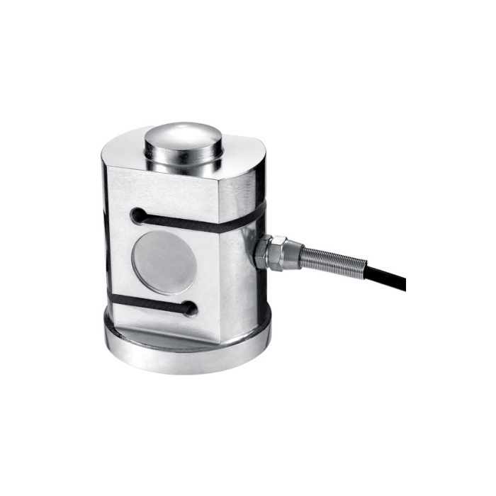
METRAVON MV-LC0127 is a column compression load cell with a slotted internal measuring structure and a raised upper contact. The documented family extends from 50 kg to 30 t. Its job is to measure compression through the intended contact path; the S-like slots visible in the body do not make it a threaded tension-and-compression sensor.
Fit the column compression load cell between the actual bearing parts
The upper contact and lower support need to transfer force along the intended axis. Show the top cap, base, surrounding restraints and expected movement on the assembly drawing. The dome radius defines a contact profile, not an unrestricted angular joint. A curved top does not by itself qualify the support for lateral load, vessel uplift or an offset load that the assembly has not been assessed to carry.
Use the dimensions for the selected capacity group
Reference height increases from 76 mm for 50-500 kg to 90 mm for 1-6 t, 130 mm for 10-20 t and 150 mm for 25-30 t. The corresponding maximum base envelopes are 54, 68, 88 and 108 mm. Check the full stack height including the mating contacts. The lowest-capacity row lists two M5 base fixings, while the general plan depicts a four-position arrangement; obtain the version-specific drawing before drilling that base rather than assuming the generic plan applies to every rating.
| Item | Value | Selection notes |
|---|---|---|
| 50-500 kg H / base envelope | 76 / 54 mm | Resolve the version-specific fixing arrangement before machining. |
| 1-6 t H / base envelope | 90 / 68 mm | Reference base fixings are four M6 holes, 8 mm deep. |
| 10-20 t H / base envelope | 130 / 88 mm | Reference base fixings are four M8 holes, 10 mm deep. |
| 25-30 t H / base envelope | 150 / 108 mm | Reference base fixings are four M10 holes, 12 mm deep. |
| Working temperature | -20 to +70 deg C | Include the cable and reader in the site review. |
| Housing protection | IP66 | This entry does not establish immersion or hazardous-area approval. |
Keep the instrument scaling separate from the support design
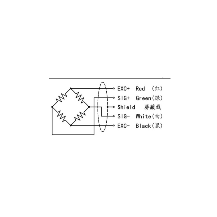
The bridge specification is 2.0 +/-0.05 mV/V, supplied with 5-12 V DC excitation. When several sensors share an indicator, assess its excitation capacity using the 380 +/-30 ohms input resistance of each bridge. Output resistance is 350 +/-5 ohms. Cable length and diameter are listed as 3 m and 5 mm. Confirm the junction arrangement and how each support will be checked. A summed display can hide an uneven support reaction, so commissioning needs a way to examine load distribution as well as total weight.
Check contact seating during loading and unloading
Establish empty indication after the final bearing parts, pipework and restraints are in place. Apply appropriate reference loading and inspect whether contact position or restraint clearance changes. A return shift after unloading calls for checking the mechanical assembly as well as the electrical channel. Nonlinearity is +/-0.03-0.05% FS, with +/-0.03% FS hysteresis and repeatability. Agree the required whole-system results at the operating load points instead of presenting those sensor entries as an installed weighing guarantee.
For a dry-mortar silo with a threaded lower mounting interface, review the distinct MV-LC0128 arrangement.
Compression duty and support replacement
Q1. Can the fixing screws be used to measure tension?
The listed measuring duty is compression through the upper contact. Base fixings position the sensor and do not establish a tensile measuring rating. If the vessel can lift, design and specify an appropriate restraint rather than treating the measuring body as an approved hold-down.
Q2. Will a taller, higher-capacity body preserve the old calibration?
The support height, contact profile and base pattern can change, and a new sensor has its own actual sensitivity. Review the bearing stack and connected electronics, then repeat the agreed system calibration. An unchanged nominal 2 mV/V entry is not sufficient evidence for retaining the old span.
Q3. Can it replace the threaded sensor used below a dry-mortar silo?
Compare both mechanical interfaces and electrical sensitivity. MV-LC0128 has an M42 x 3 bottom thread and a 1.5 mV/V nominal bridge, unlike this base-mounted 2 mV/V family. Similar compression duty does not establish interchangeable mounting or reader settings.
