


 Chinese
 Spanish
 Russian
 Portuguese
 French
 German
 Indonesian
 Thai
 Vietnamese
 Arabic
 Italian
 Turkish
 Polish
 Japanese



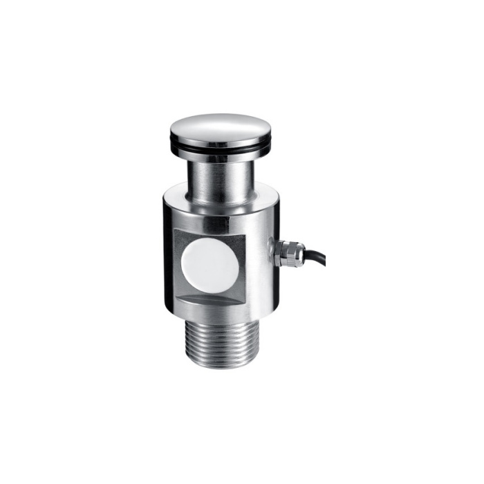
METRAVON MV-LC0128 is a load cell for dry-mortar silo supports, using a shear-column measuring body with a threaded lower connection and domed upper contact. Its documented family covers 10-30 t. Select it from the greatest reaction at an individual support, including the silo structure and its contents, rather than dividing a nominal storage capacity by the number of legs without checking the actual load distribution.
Check the threaded support and upper contact before selecting the rating
The reference drawing gives 139 mm overall height, a 64 mm main-body diameter and a 54 mm upper contact diameter. The lower external thread is M42 x 3, with a 33 mm lower thread-section reference. The dome is designated SR100. Send the mating support drawing to confirm seating, thread engagement and installed height. These dimensions do not define the capacity of the surrounding bracket or supply an approved uplift restraint for the silo.
| Item | Value | Selection notes |
|---|---|---|
| Capacity family | 10-30 t | Check the highest individual support reaction. |
| Overall height / body diameter | 139 / 64 mm | Allow for both mating supports and cable clearance. |
| Bottom connection | M42 x 3 | External thread; verify the receiving part and engagement. |
| Upper contact diameter / radius | 54 mm / SR100 | Match the bearing surface; do not infer a permitted tilt angle. |
| Cable / temperature | 3 m / -20 to +70 deg C | Listed cable diameter is 5 mm. |
| Housing protection | IP66 | Confirm the enclosure and termination requirements for the site. |
Select a load cell for dry-mortar silo operating forces, not just static contents
Provide empty silo mass, maximum stored mass, support layout and the likely centre-of-gravity positions. Review loading during pneumatic filling, discharge and any vibration equipment, together with attached pipes and chutes. Restraints must control the required movement without creating a changing force bypass during weighing. A qualitative resistance-to-offset description is not a numerical wind or lateral-load rating; the complete support assembly needs its own mechanical assessment.
Use the 1.5 mV/V sensitivity when configuring the weighing channel
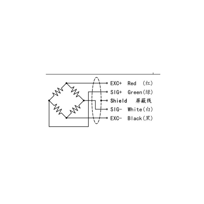
This model lists 1.5 +/-0.05 mV/V, not the 2 mV/V value found on many other weighing sensors. Excitation is 5-12 V DC; input and output resistances are 380 +/-30 and 350 +/-5 ohms. A reader retained from another installation needs its range and calibration checked against the offered sensor. State the required PLC connection separately: an mV/V bridge does not directly supply a 4-20 mA loop or an RS485 communication channel.
Prove the measurement with the silo in its relevant operating states
Define a practical reference-loading or material-comparison procedure before installation access is restricted. Establish empty indication and check the effects of the connected fill line, discharge equipment and vibration system under controlled conditions. Do not increase filtering simply to conceal a mechanical interaction. Nonlinearity is specified as +/-0.1-0.3% FS, with +/-0.1% FS hysteresis, repeatability and creep. Use the confirmed version and agreed site tests to assess inventory performance; do not transfer a tighter error figure from another model.
Silo restraints, inventory and reader settings
Q1. Does the threaded base make this a complete anti-uplift module?
It establishes one mechanical connection, not the performance of the complete support. Include the bracket, top contact, lateral guidance and uplift restraint in the project review. State which of those parts are actually included in the supply.
Q2. Can silo weight be converted directly into material level?
The sensor measures force, not level. A level estimate also depends on silo geometry and the material bulk density, which can vary with composition and compaction. Define the conversion assumptions and how they will be checked if the process needs a level indication rather than mass inventory.
Q3. Can an existing 2 mV/V instrument retain its old span?
The nominal sensitivity here is 1.5 mV/V. Confirm that the reader accepts the actual bridge and selected capacity, then calibrate the installed support system. Merely obtaining a plausible zero does not establish correct gain across the stored-mass range.
