


 Chinese
 Spanish
 Russian
 Portuguese
 French
 German
 Indonesian
 Thai
 Vietnamese
 Arabic
 Italian
 Turkish
 Polish
 Japanese



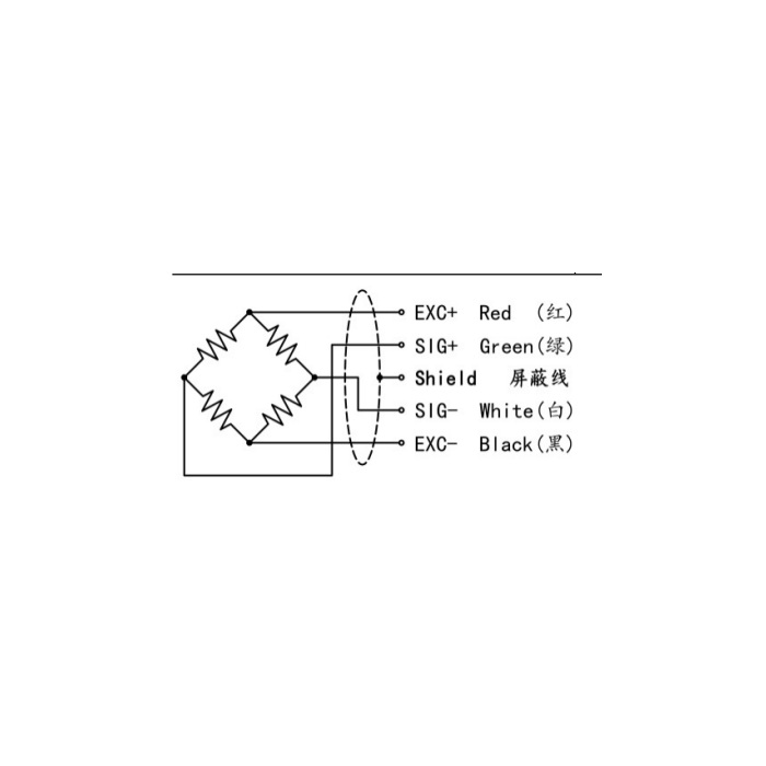
METRAVON MV-LC0126 is a parallel beam load cell for platform scales, hoppers and quantitative packaging equipment. The 50-500 kg family is documented with corner-error correction. That feature is useful for platform weighing, but it does not establish an unrestricted platform size or an accuracy guarantee at every possible load position. Submit the platform layout with the required capacity.
Define where the platform load will be placed
A central test weight does not reproduce an operator placing a container near an edge or a package arriving off centre. State the platform length and width, its tare weight, maximum net load and the positions that must produce an acceptable reading. Include any guides, stops or conveyor transfers that can push the platform sideways. Capacity selection must cover the supported dead load as well as the material, while the proposed geometry needs a separate eccentric-loading review.
Mount the parallel beam load cell on the correct end pads
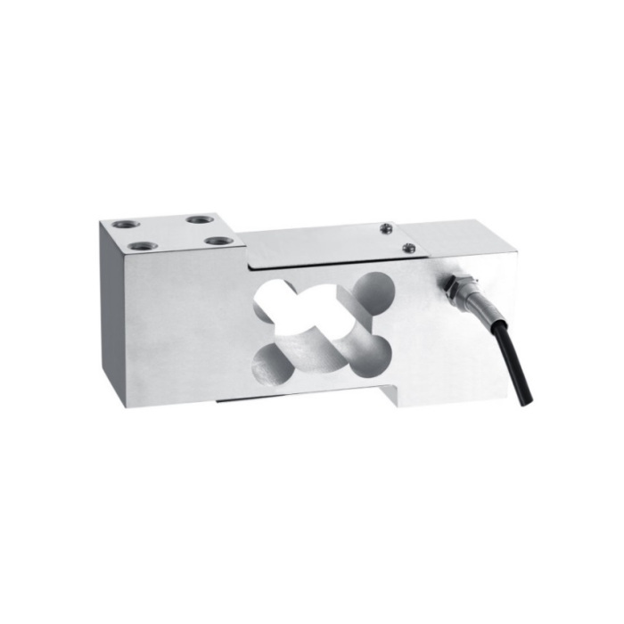
The reference envelope is 160 mm long, 72 mm high and 50 mm wide. Eight M10 holes are shown, four at each end, with 12 mm depth and a 30 by 32 mm pattern at each pad. These are drawing dimensions, not a bolt torque or thread-pitch specification. Obtain the complete installation drawing to identify the fixed and loaded ends; cable location alone is not an installation instruction. Check screw engagement against both the threaded depth and the mating plate thickness.
| Item | Value | Selection notes |
|---|---|---|
| Capacity family | 50-500 kg | Include platform tare and the required load positions. |
| Reference L / H / W | 160 / 72 / 50 mm | Check room for the complete supported platform. |
| End-pad hole pattern | 30 x 32 mm | Four M10 holes at each end; eight in total. |
| Threaded-hole depth | 12 mm | Confirm engagement and fastener details on the drawing. |
| Temperature / housing | -20 to +70 deg C / IP66 | Review cable termination and washdown conditions separately. |
| Nominal sensitivity | 2.0 +/-0.05 mV/V | Condition the bridge before connecting a PLC analogue input. |
Separate static weighing from a packaging cutoff decision
Rated sensitivity is 2.0 +/-0.05 mV/V and excitation is 5-12 V DC. The bridge has 380 +/-30 ohms input resistance and 350 +/-5 ohms output resistance, with a listed 3 m cable of 5 mm diameter. A packaging system also needs a suitable reader, filtering and a defined time to take the weight. Material still falling after a feed command and vibration from the machine affect the batch result. The sensor table alone does not specify achievable fill speed or final batch error.
Accept the assembled platform at its working positions
Complete the mounting, guards and cable routing before setting tare and span. Compare a suitable reference load at the centre and at the agreed off-centre positions, then repeat after removing the load. Investigate contact with stops or adjacent machinery if the result changes with position. The documented nonlinearity is +/-0.03-0.05% FS; hysteresis, repeatability and creep are each +/-0.03% FS. Do not attach an unstated duration to the creep figure or substitute it for the platform acceptance results.
Compare MV-LC0129 when the assembly needs a central compression contact rather than two end mounting pads.
Platform size and edge-loading checks
Q1. Does corner-error correction mean any size of platform is suitable?
No permitted platform dimensions or unlimited eccentric-load envelope follow from that description. Provide the proposed platform and load positions for review, then verify the complete assembly at those positions. A central calibration alone cannot demonstrate edge-loading performance.
Q2. Can the platform touch a guide rail if the display is zeroed afterwards?
Contact can divert part of the applied force away from the measuring path. Zeroing at one position does not correct a force bypass that changes as the platform moves or loads. Maintain the intended clearance and repeat the positional checks after any guide adjustment.
Q3. Should this model be chosen instead of an enclosed round sensor?
Compare attachment geometry rather than the shared parallel-beam principle. MV-LC0126 has two end pads with a rectangular body; MV-LC0129 introduces compression through a central contact above a square base. Neither arrangement can be treated as a drop-in replacement for the other.
