


 Chinese
 Spanish
 Russian
 Portuguese
 French
 German
 Indonesian
 Thai
 Vietnamese
 Arabic
 Italian
 Turkish
 Polish
 Japanese



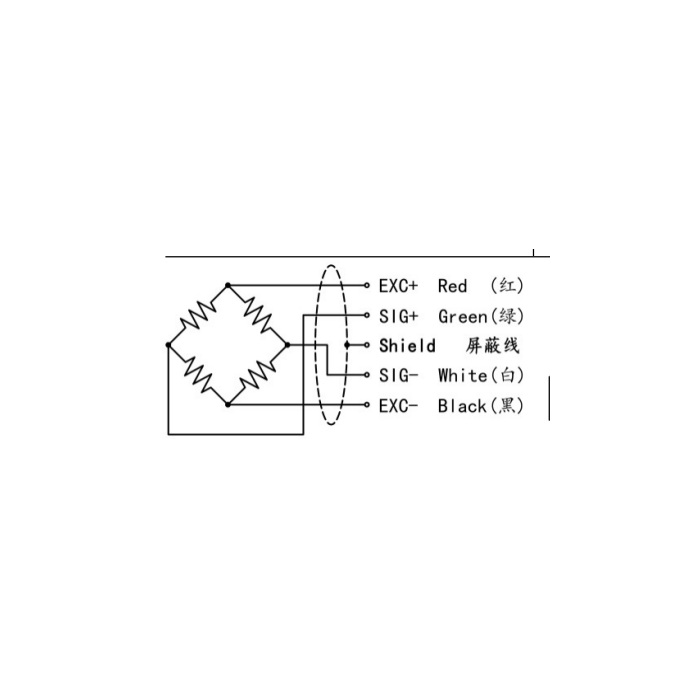
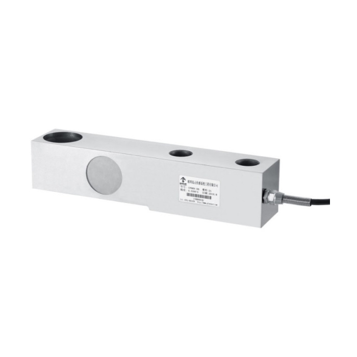
METRAVON MV-LC0125 is a cantilever beam load cell for platform, hopper and tank weighing assemblies. Its single-ended shear-beam arrangement has a bolted fixing end and a separate recessed load end. The documented family covers 500 kg to 20 t, with dimensions grouped by capacity. Choose the beam together with its mounting surface and load-introduction hardware, not from rated capacity alone.
A cantilever beam load cell can change holes without changing its envelope
The 500 kg-2 t group and the 3 t row both show a 203 mm length, 36.5 mm width and 43 mm height. Their fixed-end hole diameter D2 is different: 13 mm for the lower group and 15 mm at 3 t. Fixed-end centre spacing L5 remains 64 mm. An apparently identical replacement therefore needs a bolt and base review. Confirm the exact drawing row before releasing a mounting plate for manufacture or retaining the old fixing hardware.
| Item | Value | Selection notes |
|---|---|---|
| 500 kg-2 t L / W / H | 203 / 36.5 / 43 mm | Two 13 mm fixing holes; L5 spacing is 64 mm. |
| 3 t L / W / H | 203 / 36.5 / 43 mm | D2 increases to 15 mm despite the same body envelope. |
| 5 t length / D2 | 235 / 20 mm | Compare the recessed load end as well as the fixing end. |
| 10 t length / D2 | 279 / 28 mm | A capacity increase changes the mechanical footprint. |
| Working temperature | -20 to +70 deg C | Select the steel version for the actual installation. |
| Safe overload | 150% FS | Do not use this entry as a continuous weighing range. |
Support the fixing end and leave the measuring section free
Provide the base drawing, fixing arrangement and the part that introduces force into the recessed load end. The beam must carry the intended load without the moving structure touching the base or an external stop during normal weighing. Side forces from a hopper connection, a rigid pipe or a misaligned loading piece can alter the measured reaction. A bare beam is not a complete tank support: identify restraints, overload stops and any uplift provision as assembly items on the offer.
Size from the largest support reaction, then check the installation space
For a multi-support vessel, start with the empty weight, maximum contents and centre-of-gravity positions. Equal division by the number of supports is only a starting calculation when loading is not evenly distributed. Filling impact, agitation and maintenance loads also need assessment. The 5 t reference is 235 mm long and uses 20 mm D2 holes; at 10 t these become 279 and 28 mm. A larger rating can require a different base, load fitting and surrounding clearance rather than a simple electronic adjustment.
Commission the beam through its installed loading piece
Connect the 2.0 +/-0.05 mV/V bridge to a compatible weighing indicator or conditioner with 5-12 V DC excitation. Input and output resistances are 380 +/-30 and 350 +/-5 ohms. The listed cable is 3 m long and 5 mm in diameter. After final assembly, check empty indication, reference loads, return after unloading and the relevant platform or vessel load positions. The +/-0.03-0.05% FS nonlinearity entry describes the sensor; mounting and loading effects remain part of the completed weighing result.
Replacement bases and loading hardware
Q1. Can the existing 500 kg-2 t base be used with the 3 t version?
The body dimensions and fixing pitch match, but the specified fixing-hole diameter changes. Compare bolts, bearing surfaces, load-end hardware and the base strength against the selected drawing. Reusing a base is a mechanical decision, not a consequence of the similar photograph.
Q2. Is the recessed load-end insert included with the sensor?
List the insert and mating support on the quotation and check their drawings. The sensor description does not establish a complete module supply. The applied force must reach the intended loading feature without rubbing or an unintended second support.
Q3. Can the same beam be used for a rapidly cycling press?
A reference application does not establish permissible cycling frequency, fatigue life or a machine safety function. Submit the full force cycle, peak events and required response for assessment. Verify the mechanical assembly and measuring channel for that duty before accepting it.
