


 Chinese
 Spanish
 Russian
 Portuguese
 French
 German
 Indonesian
 Thai
 Vietnamese
 Arabic
 Italian
 Turkish
 Polish
 Japanese



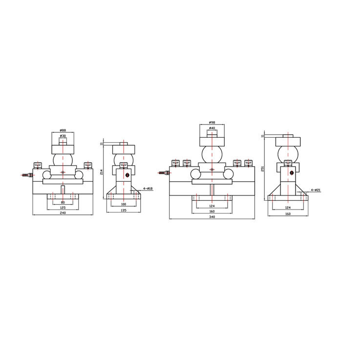
METRAVON MV-LC0119 is a double-ended shear beam load cell with a ball loading arrangement for truck scales, rail scales and related industrial weighing assemblies. The family is listed at 10-50 t. The ball and mating bearing parts are part of the force path, so a replacement enquiry needs more than the old sensor capacity and a photograph of its body.
Identify the ball contact and mating bearing parts
Supply drawings or clear measurements of the upper bearing, ball, lower support and scale structure. The documented self-aligning action does not establish an unlimited displacement or tilt angle. Check how the assembly controls lateral movement and keeps the contact seated as the platform moves. Do not retain a worn mating surface merely because a new sensor can be positioned underneath it: the actual contact condition affects how force enters the measuring assembly.
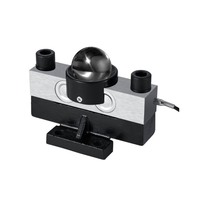
Check the double-ended shear beam load cell envelope by version
The reference drawings distinguish 20-40 t from 50 t. Their overall lengths are 240 and 340 mm, while assembly heights are 244 and 253 mm. Four base holes change from 18 to 21 mm diameter. These are substantial installation differences even though the measuring principle is shared. The family table also lists a 10 t lower limit, but no separate 10 t outline is established by those two drawings; request that version drawing before reserving its mounting space.
| Item | Value | Selection notes |
|---|---|---|
| Documented family | 10-50 t | Confirm the exact supplied capacity and matching assembly. |
| 20-40 t length / height | 240 / 244 mm | Four 18 mm base holes appear in this reference view. |
| 50 t length / height | 340 / 253 mm | The reference base holes increase to 21 mm. |
| Input / output resistance | 750 / 700 ohms | Tolerances are +/-30 ohms input and +/-5 ohms output. |
| Temperature / cable | -20 to +70 deg C / 3 m | Listed cable diameter is 5 mm. |
| Material / housing | Alloy steel / IP66 | Review bearing condition and field termination protection. |
Verify the indicator against the 750-ohm input bridge
Rated sensitivity is 2.0 +/-0.05 mV/V. Bridge input resistance is 750 +/-30 ohms and output resistance is 700 +/-5 ohms, with 5-12 V DC excitation. When several supports are connected, check the indicator excitation rating and junction arrangement for their actual electrical load. Preserve the supplied wiring identification and complete the 3 m cable routing before calibration. Similar nominal sensitivity does not establish interchangeability with a different mechanical support or a different bridge circuit.
Inspect each support before accepting a total scale reading
During reference loading, observe whether the ball remains seated and whether restraints or adjacent members make unintended contact. Compare the response at the required platform positions, then check the empty indication after unloading. A plausible total at one position can conceal a poorly seated or unevenly loaded support. The specified nonlinearity, hysteresis and repeatability are each +/-0.03% FS; agree the installed scale checks separately. Vehicle-weighing use alone does not establish legal-for-trade approval for the delivered scale.
MV-LC0120 uses a concave cradle-top arrangement rather than this exposed ball contact; compare the mating support geometry before considering another bridge design.
Ball condition and replacement fit
Q1. Can the old steel ball be used with a new sensor?
Compare the approved contact geometry and inspect wear, corrosion and seating before deciding. A retained ball also needs to suit the mating upper and lower parts. Include the complete bearing arrangement in the replacement review rather than assuming all spherical loading parts are equivalent.
Q2. Does the self-aligning arrangement eliminate the need for restraints?
It describes a load-introduction feature, not the permitted travel or restraint design of the scale. Submit the expected platform movement and existing stops. The assembled support must retain the contact while avoiding unintended force paths during weighing.
Q3. Will the 50 t version fit a 20-40 t mounting space?
The reference length increases by 100 mm and the base-hole diameter changes as well. Compare the foundation, full bearing stack and cable access. A higher load rating is not a reason to bypass those installation checks.
