


 Chinese
 Spanish
 Russian
 Portuguese
 French
 German
 Indonesian
 Thai
 Vietnamese
 Arabic
 Italian
 Turkish
 Polish
 Japanese



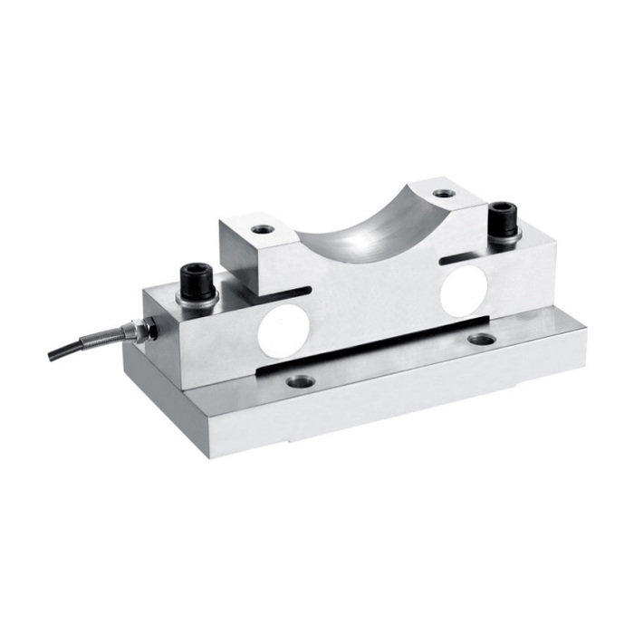
METRAVON MV-LC0120 is a cradle-top bridge load cell with a double-shear measuring structure. The reference application list includes ladle scales, crane scales and other industrial load-monitoring assemblies. Its concave upper seat is a different loading interface from a ball-top bridge support. The documented range is 5-20 t, with separate 5 t and 10-20 t dimensional rows.
Start with the supported member and its contact profile
Show the member that bears on the upper seat, including its contact shape, load direction and expected movement. The 5 t drawing gives seat radius R60, while the 10-20 t row gives R83. Those profile references do not specify a permissible rocking angle, friction condition or an arbitrary mating-cylinder size. Resolve the bearing pair and retention arrangement before selecting the assembly. Do not machine the mating support from a product photograph.
| Item | Value | Selection notes |
|---|---|---|
| 5 t L / W / H | 240 / 120 / 100 mm | Upper loading seat is designated R60. |
| 10-20 t L / W / H | 300 / 135 / 127 mm | The upper loading-seat reference becomes R83. |
| 5 t base holes / threads | 14 mm / M12 x 1.75 | Four through-holes and two thread positions are shown. |
| 10-20 t holes / threads | 18 mm / M16 x 2 | Check the complete pattern before reusing a base. |
| Cable / temperature | 3 m / -20 to +70 deg C | The listed cable is 5 mm in diameter. |
| Safe-overload entry | 150% FS | This does not establish lifting-assembly certification. |
Allow for the larger cradle-top bridge load cell base
At 5 t the listed L, W and H are 240, 120 and 100 mm. The 10-20 t group changes them to 300, 135 and 127 mm. Four base-hole diameters increase from 14 to 18 mm; the two thread designations change from M12 x 1.75 to M16 x 2. Compare the complete base and top-seat drawings together. Raising the capacity changes both installed height and contact geometry, not just the indicator range.
Confirm which nominal sensitivity is being supplied
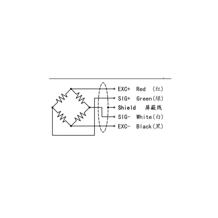
The output entry spans 1.5-2.0 mV/V with a listed +/-0.05 mV/V tolerance. Do not assign either nominal value to a capacity row without the offered sensor specification. The electrical table gives 750 +/-30 ohms input resistance, 700 +/-5 ohms output resistance and 5-12 V DC excitation. Request the actual rated output for the reader setup, then calibrate through the intended cradle and supported member. Identify any transmitter or PLC interface as a separate supplied item.
Test seating after the load has moved and returned
Define representative loading positions and any movement of the supported member during operation. Compare readings after repeated seating at the same reference condition and inspect whether the contact rubs against restraints. Published nonlinearity is +/-0.05-0.1% FS, with +/-0.05% FS hysteresis, repeatability and creep. No creep duration or dynamic response is established by those values. For crane or lifting-related duty, obtain the structural and protective-function evidence required for the complete assembly; a measuring capacity is not its approved working-load limit.
Cradle fit and return to the weighing position
Q1. Is the complete 5-20 t range one mechanically interchangeable assembly?
No. The 5 t and 10-20 t rows differ in length, width, height, hole size, threads and seat radius. Specify the required version before approving the support fabrication. Even an unchanged applied load does not make the two outlines interchangeable.
Q2. Does automatic return mean the support may be allowed to slide freely?
The description does not quantify travel, sliding conditions or allowed side force. Provide the operating movement and restraint arrangement for assessment. Check repeat seating with the assembled contact instead of treating automatic return as an unrestricted-motion rating.
