


 Chinese
 Spanish
 Russian
 Portuguese
 French
 German
 Indonesian
 Thai
 Vietnamese
 Arabic
 Italian
 Turkish
 Polish
 Japanese



METRAVON MV-LC0105 is a fixed-pulley load cell with a central cradle seat and end-supported double-shear-beam structure. Its documented family covers 2-50 t for industrial load monitoring. Choose it from the resultant force at the pulley support and the actual bearing arrangement. Neither a rope-tension value nor a hook-load label alone defines the force that this sensor must carry.
Calculate the pulley-support reaction from the rope path
Provide the incoming and outgoing rope directions, tension conditions and the pulley and bearing drawings. The support reaction depends on how the rope forces combine, including any unequal tensions relevant to the application. Identify the direction of that resultant at the sensor seat and the surrounding restraints. A fixed multiplier based only on the name fixed pulley is not a reliable project input. Keep the intended displayed quantity distinct from the measured support reaction.
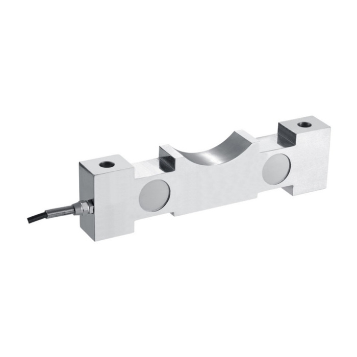
Check the fixed-pulley load cell saddle and end supports
The 2 t and 3 t versions share 250 mm length, 65 mm height, 210 mm end-hole centres and 13 mm holes, but width changes from 32 to 38 mm. At 5 t and 10 t the outer envelope is 300 by 44 by 80 mm, with 250 mm end-hole centres and 17 mm holes; the saddle-related H2 reference changes from 18 to 20 mm. Compare the complete seating geometry, not just the two fixing centres. Matching external dimensions do not establish identical load introduction.
| Item | Value | Selection notes |
|---|---|---|
| 2 t / 3 t widths | 32 / 38 mm | Both have 250 mm length, 210 mm end-hole centres and 13 mm holes. |
| 5 t / 10 t L / W / H | 300 / 44 / 80 mm | The H2 reference differs: 18 mm at 5 t and 20 mm at 10 t. |
| 15-20 t length / end centres | 350 / 295 mm | End holes are 22 mm in diameter. |
| 30 t length / end centres | 410 / 340 mm | End holes increase to 26 mm. |
| 50 t length / end centres | 460 / 360 mm | End holes are 32 mm in diameter. |
| Temperature / housing | -20 to +70 deg C / IP66 | Confirm the steel version and protection of field wiring. |
Review the larger reaction ranges before adapting the frame
The 15-20 t group uses a 350 mm body and 295 mm end-hole centres. At 30 t these become 410 and 340 mm, while 50 t uses 460 and 360 mm. Confirm base strength, contact radius, bearing seat and access for the actual assembly. The beam is a measuring component, not a complete supplied pulley with bearings or an automatically approved lifting support. Identify the mechanical parts and structural evidence required for the project separately.
Verify the monitor using the accepted pulley geometry
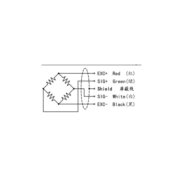
The bridge gives 1.5 +/-0.05 mV/V at 5-12 V DC excitation; input and output resistance are 750 +/-30 and 700 +/-5 ohms. The cable is listed as 3 m long and 5 mm in diameter. Connect the final conditioner and confirm the engineering-unit conversion with suitable reference conditions through the real support. Compare repeated loading and release without changing the rope path. The +/-0.05-0.1% FS nonlinearity entry does not establish the accuracy of an unverified hook-load conversion or alarm chain.
Compare MV-LC0106 when the support drawing requires a raised parallel-beam loading interface instead of this concave saddle.
Rope reaction and retained saddle parts
Q1. Can the monitor use twice the rope tension as a universal pulley load?
The vector directions and actual tensions determine the reaction. Provide the rope geometry and define the conversion for the approved operating arrangement. Do not use one multiplier for every wrap or reeving layout.
Q2. Can the 10 t version reuse the 5 t saddle just because the envelope matches?
The outer dimensions and fixing centres match, but H2 differs in the drawing. Check the saddle, contact position and complete bearing stack before accepting retained parts. Repeat the system references after the mechanical version is confirmed.
Q3. Does the sensor model include the pulley and overload protection?
Specify the pulley, bearings, frame, conditioner and any alarm or protective controller as separate scope items. The sensor specification does not establish their inclusion or the approval of the complete machine function.
