


 Chinese
 Spanish
 Russian
 Portuguese
 French
 German
 Indonesian
 Thai
 Vietnamese
 Arabic
 Italian
 Turkish
 Polish
 Japanese



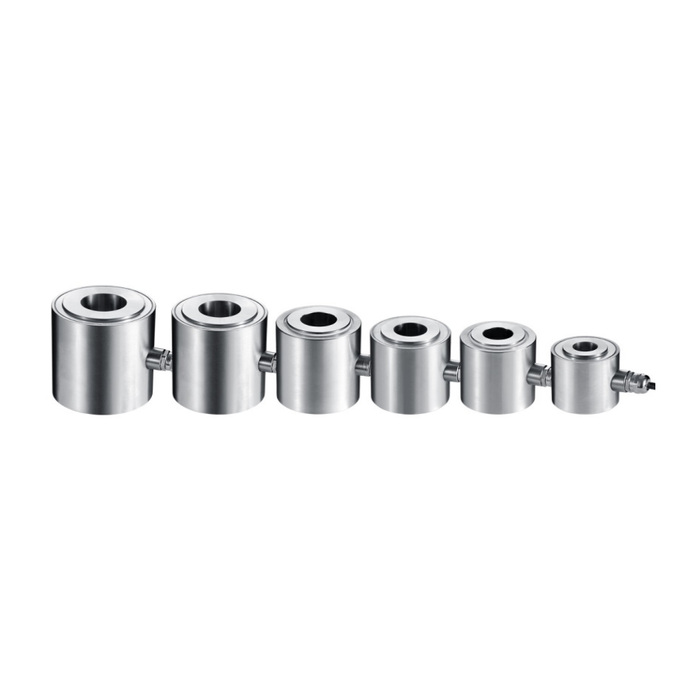
METRAVON MV-LC0104 is a through-hole load cell for bolt-preload measurement and axial compression fixtures. A bolt or shaft passes through the bore while force is transferred through the annular bearing faces. It is not a pin that measures shear across a shaft. Select bore clearance, bearing support and measuring capacity together so that the proposed clamping arrangement loads the intended faces.
Fit the through-hole load cell to the actual bolt and bearing stack
The 120 kN reference uses a 16.1 mm bore and 45 mm outside diameter, while the 400 kN row increases them to 30.1 and 69 mm. Do not infer a universal bolt fit from the nominal thread diameter: submit the actual shank, thread, coating and assembly clearances. Check the washer or bearing-piece geometry and whether it supports the intended annular area without touching an unintended housing surface. Concentric contact matters as well as enough clearance to slide the sensor into place.
| Item | Value | Selection notes |
|---|---|---|
| 120 kN bore / outside diameter | 16.1 / 45 mm | Body-height reference H is 45 mm. |
| 180 kN bore / outside diameter | 20.1 / 51 mm | Body-height reference H is 55 mm. |
| 210 kN bore / outside diameter | 22.1 / 54 mm | Body-height reference H is 58 mm. |
| 240 kN bore / outside diameter | 24.1 / 57 mm | Body-height reference H is 65 mm. |
| 320 kN bore / outside diameter | 27.1 / 64 mm | Body-height reference H is 72 mm. |
| 400 kN bore / outside diameter | 30.1 / 69 mm | Body-height reference H is 76 mm; include the raised faces. |
| Protection / temperature | IP65 / -20 to +70 deg C | Confirm material and cable-termination exposure. |
Reserve space for the raised faces, not just body height H
Body-height reference H increases from 45 mm at 120 kN to 76 mm at 400 kN. The drawing separately marks H1 = 2 mm projections at the bearing faces. Use the complete axial drawing for the assembled stack instead of treating H as an all-inclusive installed length. Include the cable gland, protected cable bend and tightening-tool access. Check that a rotating bearing member does not drag the cable or force the sensor body to follow the tightening motion.
Resolve the rating before treating a dimensional row as an offer
The specification panel states 120-400 kN, while the dimensional table also contains 500 and 600 kN rows. Those additional outlines do not establish the supplied version or all its performance conditions. Request an exact rating and drawing for a higher-load project before approving the design. Within the documented range, use the actual clamp-force interval and exceptional loads to choose the sensor, not an unverified conversion from tightening torque alone.
Check preload with the final bearing pieces and measuring channel
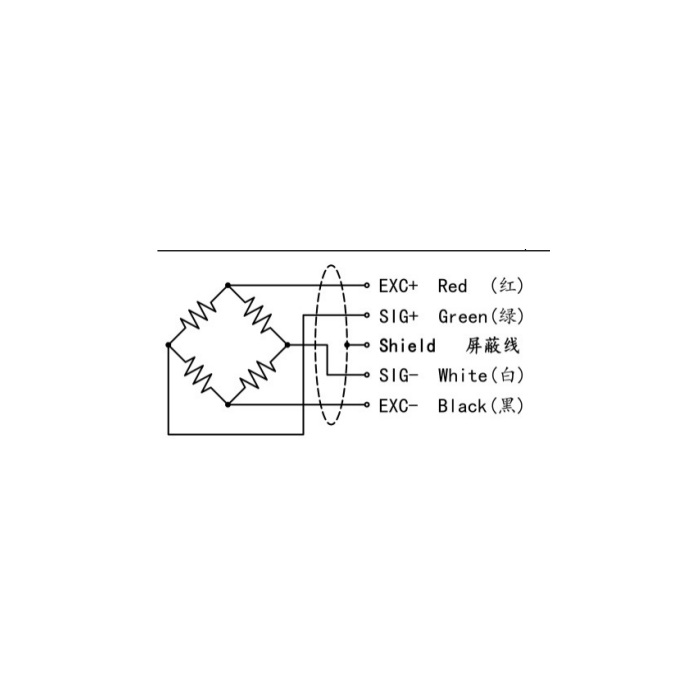
Rated output is 1.5 +/-0.05 mV/V with 5-12 V DC excitation. The bridge is listed at 750 +/-30 ohms input and 700 +/-5 ohms output. Route the 3 m cable of 5 mm diameter before comparing known axial loads through the intended bearing stack. For retained-preload measurements, define when the reading is taken and the relevant temperature and settling conditions. Nonlinearity is +/-0.3-0.5% FS; an indicated clamp force does not by itself validate the torque procedure or the entire joint design.
Bolt preload and confirmed capacity
Q1. Can preload be calculated from tightening torque instead of calibrating the channel?
Torque and axial clamp force are different quantities, and their relationship depends on the actual joint and friction conditions. This sensor is intended to measure the axial force through its bearing faces. Validate the measuring stack and the joint procedure separately rather than assigning a universal torque-to-force factor.
Q2. Are the 500 and 600 kN versions automatically available?
The dimensional rows alone are not supply confirmation. Obtain the exact offered model configuration, rating, electrical data and drawing before reserving the higher load in a project. The 120-400 kN specification panel must not silently be extended from the outline table.
Q3. Can the central bore carry the measuring force by pressing against the bolt sideways?
The documented arrangement measures axial compression at the bearing faces. Side contact at the bore is a different force path and is not an approved shear-pin measurement. Review bolt clearance and bearing alignment so that the intended axial load reaches the sensor.
