


 Chinese
 Spanish
 Russian
 Portuguese
 French
 German
 Indonesian
 Thai
 Vietnamese
 Arabic
 Italian
 Turkish
 Polish
 Japanese



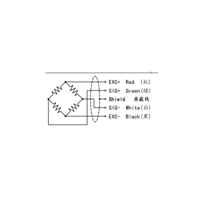
METRAVON MV-LC0103 is a torsion-ring compression load cell for industrial force and weighing supports. Torsion ring describes the measuring structure; the specified quantity is load, not torque in N m. The documented family extends from 2.2 to 330 t and uses a 2.85 mV/V nominal bridge. Review the exact support geometry and instrument headroom before retaining hardware or settings from another compression sensor.
Check the torsion-ring compression load cell height at the selected rating
The 2.2 t and 4.7 t rows both show a 60 mm base diameter and 43 mm height H, while the upper A diameter changes from 49 to 52 mm. The 47 t and 68 t versions both have 130 mm A and base diameters, but H changes from 75 to 85 mm. At 100 and 150 t the corresponding diameter remains 150 mm while H changes from 90 to 100 mm. A shared circular outline therefore does not establish an unchanged bearing stack.
| Item | Value | Selection notes |
|---|---|---|
| 2.2 t / 4.7 t height | 43 mm | Both bases are 60 mm; A diameters are 49 and 52 mm. |
| 10 / 15 / 22 t height | 50 mm | A and base diameters are 75 mm for these reference rows. |
| 47 t / 68 t height | 75 / 85 mm | A and base diameters remain 130 mm. |
| 100 t / 150 t height | 90 / 100 mm | The shared A and base diameter is 150 mm. |
| 220 t / 330 t height | 130 / 145 mm | The higher reference rows use 225 mm A and base diameters. |
| Temperature / enclosure | -20 to +70 deg C / IP66 | Confirm steel version, bearing assembly and field termination. |
Keep small-version fixings separate from the larger locating arrangement
The lower-capacity drawing shows a four-M5 fixing arrangement; the 10-330 t section introduces a different underside locating feature. Obtain the chosen rating drawing and resolve the lower bearing or location interface before making the base. Match the upper compression contact and the surrounding restraints as well. The ring form does not establish a central through-bolt interface, unrestricted lateral movement or an interchangeable mounting pattern with a spoke load cell.
Check reader range for 2.85 mV/V rather than copying a 2 mV/V setup
At 10 V excitation the nominal rated signal is 28.5 mV, calculated from 2.85 mV/V. Check the bridge input range and gain for the actual delivered output before applying full reference load. Listed resistances are 1450 +/-50 ohms input and 1400 +/-5 ohms output, with 5-12 V DC excitation. A matching cable connector alone does not establish that an old indicator accepts this signal or the selected full-scale load.
Reference the completed support at the useful process loads
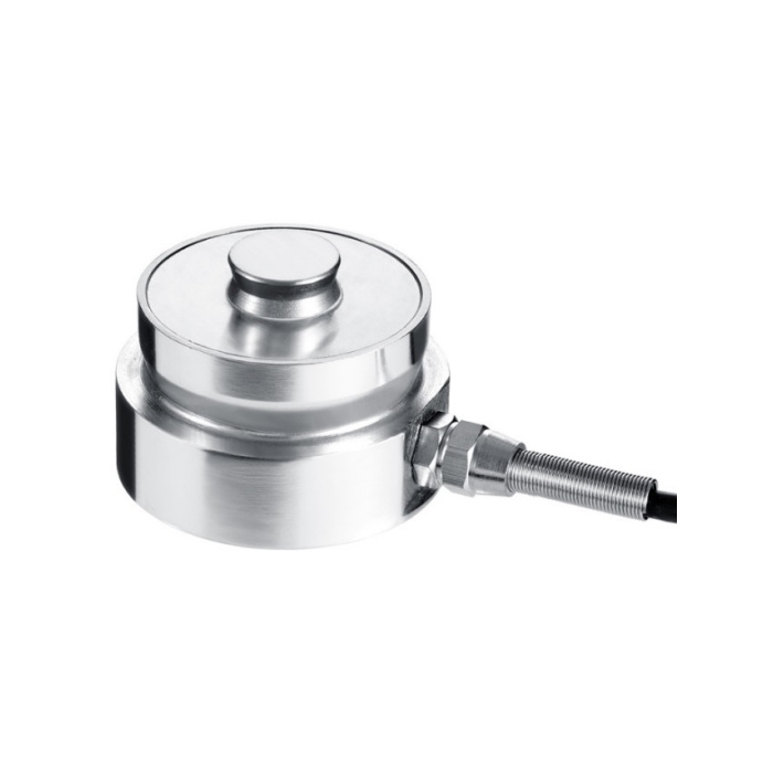
Install the actual bearing parts, restraints and final 3 m cable of 5 mm diameter before setting zero and span. Compare appropriate loading and unloading references and inspect whether the contact shifts as the support settles. Nonlinearity is +/-0.05-0.1% FS, hysteresis +/-0.08% FS and repeatability +/-0.05% FS. Define the whole-system acceptance at the operating loads instead of substituting one of these sensor entries for an installed error budget. The listed 150% FS safe overload is not a normal operating extension.
Compression duty and reader headroom
Q1. Does torsion ring mean the output measures shaft torque?
No torque measurement range or N m output is established for this product. The documented configuration measures compression load. Specify a dedicated torque-measurement solution when the required quantity is rotational moment rather than support force.
Q2. Can the 68 t body replace the 47 t version without changing support height?
The reference diameter is shared, but height H increases by 10 mm. Review the top contact, lower location, restraint clearances and total bearing stack. Recheck load distribution if several supports are affected.
Q3. Can an old 2 mV/V indicator retain its gain?
The nominal sensitivity here is 2.85 mV/V. Confirm input headroom and the configuration method, then establish span with the completed support. An apparently reasonable empty zero does not verify gain or full-load input range.
