


 Chinese
 Spanish
 Russian
 Portuguese
 French
 German
 Indonesian
 Thai
 Vietnamese
 Arabic
 Italian
 Turkish
 Polish
 Japanese


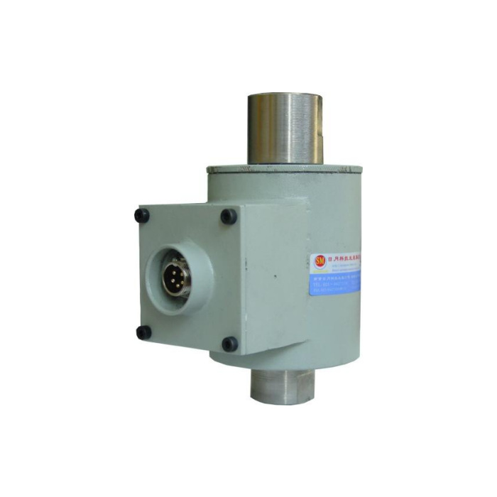

METRAVON MV-LC0102 is a tension load cell with analogue output for belt-weighing, speed-regulated weighing and automatic-feeder assemblies. The documented family is 100-5000 kg and lists 0-5 V or 4-20 mA output with a 15-36 V DC supply. It must not be configured as a passive mV/V bridge. Confirm the supplied output version and the tensile connection before selecting the controller input.
Select the tension load cell analogue output with the controller
Specify whether the project needs 0-5 V or 4-20 mA; the two entries do not establish simultaneous or field-switchable outputs. Check the PLC, RTU or data-logger input type, power arrangement and required engineering-unit span. A current-output label does not by itself establish a two-wire loop: obtain the delivered connector wiring and input/output circuit. No RS485 or Modbus RTU interface is established by the analogue options.
Do not assume that the two tensile end connections match
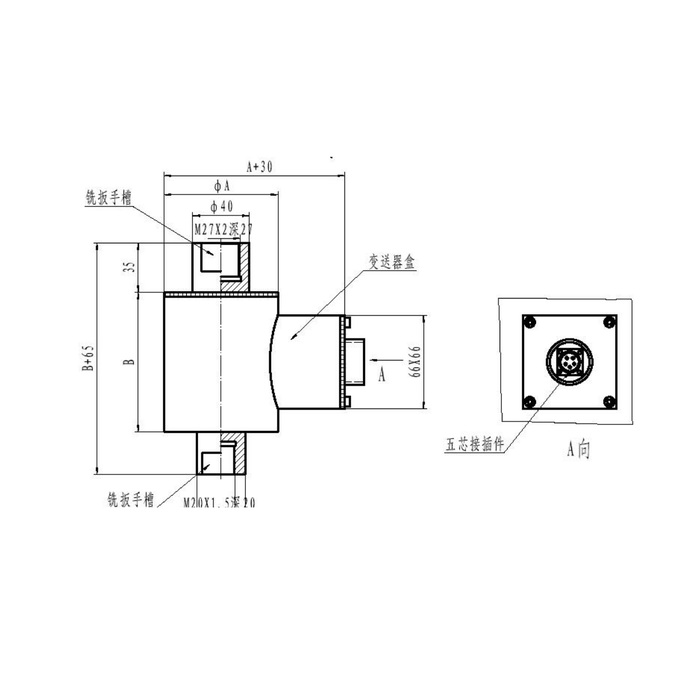
The reference drawing designates an upper M27 x 2 internal thread with a 27 mm depth and a lower M20 x 1.5 internal thread with a 20 mm depth. Include both mating fittings and the anti-rotation or locking arrangement in the assembly review. Body diameter and length are shown using variable references, so obtain the selected-capacity outline before reserving the connected length. A pair of identical old fittings cannot be approved merely because the sensor is described as a tension link.
| Item | Value | Selection notes |
|---|---|---|
| Family range | 100-5000 kg | Confirm the rated tensile load and its output span. |
| Output options | 0-5 V / 4-20 mA | Select the actual version; do not assume both outputs are available together. |
| Operating supply | 15-36 V DC | Not the excitation setting used for a passive bridge sensor. |
| Upper thread / depth | M27 x 2 / 27 mm | Review the exact mating fitting and engagement. |
| Lower thread / depth | M20 x 1.5 / 20 mm | The lower connection is not identical to the upper one. |
| Connection reference | Five-contact connector | Use the delivered wiring, not an assumed two-wire loop pinout. |
Keep the transmitter enclosure and connector within the installation review
The drawing shows a side transmitter enclosure and five-contact connector. Allow access for mating and retention without pulling the tensile link sideways. IP67/IP68 appear as protection entries, but the offered version and any required immersion conditions need confirmation. Include the mated connector and cable exposure rather than applying the body rating to an unspecified plug. Operating temperature is listed as -40 to +85 deg C; check the complete powered channel for the actual site.
Verify force scaling before interpreting feeder performance
Apply appropriate reference tension through the approved end fittings, then compare the actual controller value across the required operating interval. For a belt or feed system, identify the additional speed or mechanical information used to obtain the process quantity; a tension signal alone is not a complete mass-flow measurement. The listed precision entry is 0.05% FS, and safe load limit is 200% FS. Neither establishes the final feed-rate error, transient response or a protective function of the whole machine.
Analogue-input matching and unequal end threads
Q1. Can it connect directly to a PLC analogue input?
It can be considered where the delivered voltage or current output matches the input, but supply, circuit type, connector wiring, input loading and span still need confirmation. Verify the physical signal and displayed engineering units with reference tension before release.
Q2. Can both old M27 fittings be reused?
The reference lower thread is M20 x 1.5, not M27 x 2. Compare both ends and the full connected assembly before accepting retained hardware. Request the offered capacity drawing and fitting scope with the quotation.
Q3. Does a 4-20 mA option mean no external power wiring is required?
No power or loop topology should be inferred from the output name. The listed supply is 15-36 V DC and the connector has separate input/output designations in the reference drawing. Obtain the exact circuit and connect it according to the delivered version.
