


 Chinese
 Spanish
 Russian
 Portuguese
 French
 German
 Indonesian
 Thai
 Vietnamese
 Arabic
 Italian
 Turkish
 Polish
 Japanese


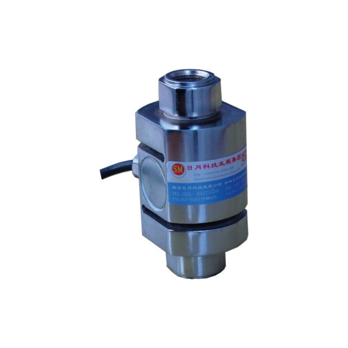

METRAVON MV-LC0098 is a compact S-type load cell for axial tension and compression measurement. Its S-type parallel-beam measuring structure is enclosed in a compact body with opposed threaded connections, rather than the exposed S-shaped outline of some other force sensors. The specified measuring range is 100-2000 kg. Select it with the required coupling details and the force directions used by the fixture.
Connect the compact S-type load cell from its selected drawing row
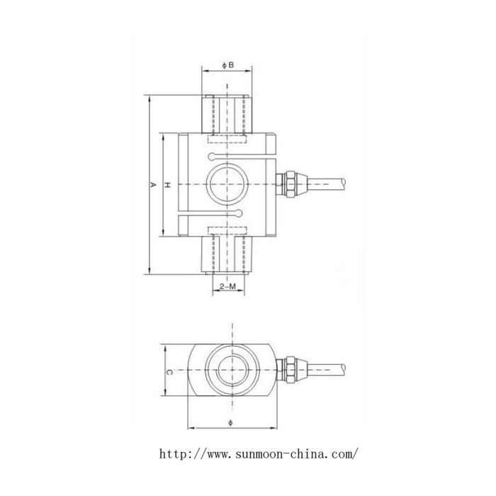
The dimensional reference separates 100-500 kg, 700 kg and a larger 1-5 t body group. For a project within the specified 100-2000 kg range, identify the actual rating before using those rows. The first two rows show an 88 mm overall A reference and 58 mm body-height H reference with an M16 x 1.5 end designation. The larger row changes A and H to 120 and 68 mm and gives an M22 designation without a stated pitch. Obtain the complete offered thread details; the larger dimensional rows do not automatically extend the specified measuring range.
| Item | Value | Selection notes |
|---|---|---|
| Specified measuring range | 100-2000 kg | Confirm the actual rating and matching dimensional row. |
| 100-500 kg / 700 kg A / H | 88 / 58 mm | The listed end designation is M16 x 1.5. |
| Larger-group A / H | 120 / 68 mm | The M22 designation needs full thread confirmation. |
| Input / output resistance | 380 / 350 ohms | Tolerances are +/-5 ohms input and +/-2 ohms output. |
| Excitation / protection | 10-12 V DC / IP67 | Check the delivered pin or wire identification before connection. |
| Listed precision entry | 0.05% FS | Not an automatic accuracy guarantee for the assembled push-pull fixture. |
Use the documented bridge supply rather than a generic excitation setting
This model lists 10-12 V DC, not a presumed 5-12 V operating range. Rated sensitivity is 2.0 +/-0.015 mV/V. Check the reader excitation and input range before retaining an old force indicator. The table and circuit sketch do not consistently identify the signal-pair polarity by colour, so obtain the delivered wiring identification and verify sign with a known force. Do not approve the connection from a colour convention borrowed from another model.
Make reversal part of the acceptance test
Define tensile and compressive operating points, preload and the movement at each coupling. Verify the required force signs and reference values in both directions, then compare return after release. A gain set with a tensile reference does not establish the compression result or remove bending introduced by the fixture. The listed 0.05% FS precision entry belongs to the documented sensor conditions; acceptance needs the final couplings, acquisition equipment and actual test sequence.
Keep the safe-load entry separate from the fixture rating
The sensor table lists a 200% FS safe load limit and an operating temperature of -40 to +85 deg C. Neither entry establishes fatigue performance, a lifting working-load limit or the ratings of the attached hardware. Review the expected peaks and environment with the complete force fixture. Confirm the alloy-steel or stainless-steel version and the termination protection required for its IP67 installation. Do not use a high sensor overload figure to justify an unreviewed coupling or routine above-capacity operation.
Thread definition, excitation and force reversal
Q1. Does the larger outline table prove that a 20 t version is covered by this offer?
No. The documented measuring range is 100-2000 kg. The larger dimensional rows do not establish an available higher-capacity version. A higher-load enquiry needs its own confirmed configuration, technical specification and drawing. Do not extend the measuring range from an outline row alone.
Q2. Can the reader be set to 5 V because many bridge sensors accept it?
The documented supply here is 10-12 V DC. Confirm the proposed excitation against the delivered sensor and the reader capability. A visible output at an unconfirmed voltage is not evidence that the documented performance conditions have been met.
Q3. Can the existing threaded couplings be retained?
Compare complete thread designation, engagement, connected length and alignment at the actual rating. An M22 size without pitch information is not enough to approve a replacement. Check both couplings through the reversing force sequence after the mechanical connection is accepted.
