


 Chinese
 Spanish
 Russian
 Portuguese
 French
 German
 Indonesian
 Thai
 Vietnamese
 Arabic
 Italian
 Turkish
 Polish
 Japanese


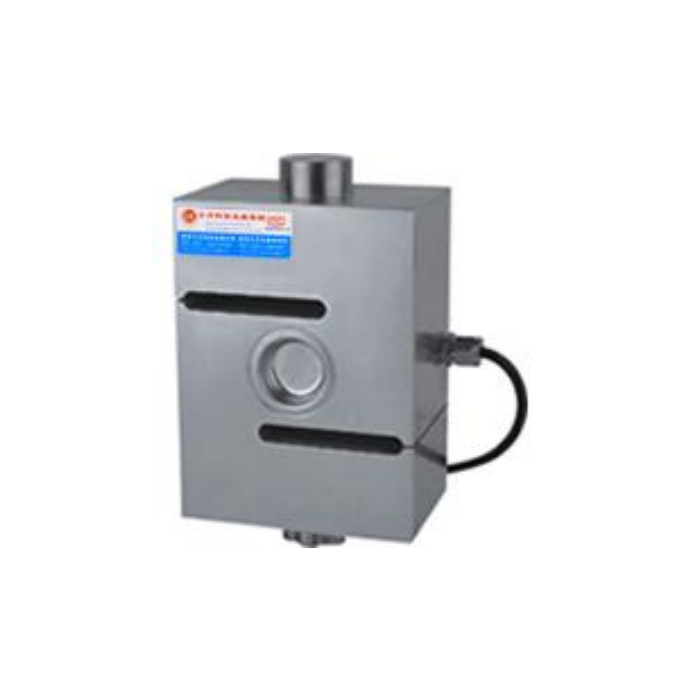

METRAVON MV-LC0097 is identified as an S-type tension and compression sensor, but its available technical entry and dimensional reference do not establish one consistent installation specification. The technical range is 500-3000 kg, while thickness annotations in the reference drawing refer to 15/20/30 t. Resolve that mismatch before ordering a replacement or machining its fixture. The information below is a verification checklist, not approval to combine those two sets of data.
Resolve the S-type load cell capacity before choosing fittings
Send the existing sensor label, required rated force, working interval and both end-connection details. Request an offered configuration whose capacity, dimensions and measuring directions appear on matching technical records. Do not infer that a body shown for a higher-tonnage group has the performance or rating of the 500-3000 kg entry. Likewise, the drawing annotations do not prove that a 15, 20 or 30 t version is available under this model reference.
| Item | Value | Selection notes |
|---|---|---|
| Technical capacity entry | 500-3000 kg | Requires a matching offered configuration and installation drawing. |
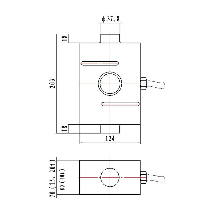
| Conflicting drawing labels | 15 / 20 / 30 t | Do not combine these thickness annotations with the lower-range panel. |
| Front-view references | 203 / 124 mm | Identification only until the correct capacity drawing is confirmed. |
| End-feature diameter reference | 37.8 mm | This does not establish an end thread or coupling rating. |
| Listed bridge output / excitation | 2.0 mV/V / 10-12 V DC | The output tolerance entry is +/-0.015 mV/V; confirm the same physical version. |
| Records needed for quotation | Capacity / drawing / connections | The unresolved combination is not a basis for interchangeability approval. |
Use the outline only to identify what still needs confirmation
The reference shows 203 mm and 124 mm front-view dimensions and a 37.8 mm end-feature diameter. They are identification clues, not a released machining basis for the listed capacity range. Obtain the full side section, end connection, locating faces and cable exit for the actual offered unit. A thread designation is not established by the circular end feature. Keep external fittings and frame fabrication on hold until the supplier confirms one complete, consistent assembly drawing.
Confirm the electrical specification for the same physical version
The technical panel lists 10-12 V DC excitation, 2.0 +/-0.015 mV/V bridge output, 380 +/-5 ohms input resistance and 350 +/-2 ohms output resistance. Check those values against the exact configuration on the offer rather than borrowing them for whichever outline happens to fit. A millivolt bridge still needs a suitable conditioner or force indicator. Ask for the delivered wiring identification and verify the indicated direction with a known reference; do not resolve conflicting colour conventions by guesswork.
Agree the release evidence and final acceptance together
Before approving the purchase, require the matched rated capacity, installation drawing, full connection details, electrical version and applicable environmental specification. The existing entries include IP67 and a 0.05% FS precision figure, but these are not a substitute for matching the physical product to its records. After that configuration is confirmed, define the tensile and compressive reference points needed by the fixture and verify sign, repeatability and return after release. A plausible unloaded zero cannot resolve a mechanical-capacity documentation conflict.
Purchase release and unmatched reference data
Q1. Can the 203 by 124 mm outline be used to make the mounting parts now?
Not while the capacity and thickness annotations remain inconsistent with the technical panel. Obtain the correct dimensional release for the actual rated version, including the end features and side section. Preparing the base from the unmatched outline risks committing the fixture to the wrong body.
Q2. Does this mean the existing sensor must immediately be replaced?
The documentation mismatch alone does not diagnose the installed unit. Identify its actual label, records and installation, then use the approved inspection and test method for that equipment. The purchasing decision needs the real unit configuration, not a guess based on this reference image.
Q3. What is needed for a usable replacement quotation?
Provide label photographs, the required rated and working forces, full attachment dimensions, reader details and operating conditions. Ask for matching capacity data and a drawing in the response. Approval should identify one complete version rather than separate unlinked capacity and outline statements.
