


 Chinese
 Spanish
 Russian
 Portuguese
 French
 German
 Indonesian
 Thai
 Vietnamese
 Arabic
 Italian
 Turkish
 Polish
 Japanese


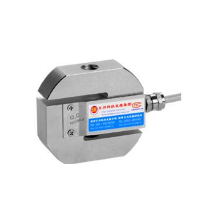

METRAVON MV-LC0096 is a compact S-type force sensor for tension and compression fixtures. The technical table specifies 500-3000 kg, while the dimensional reference includes a wider set of bodies. Within the specified range, compare the thickness and end connection at the exact rating. The clipped outer profile and central cover are not additional places to introduce the measuring force.
Fit the compact S-type force sensor by thickness as well as front size
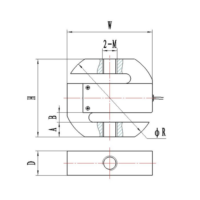
The 500 kg reference falls in a row with H64 and W70 mm, thickness D20 mm and an M12 designation. The 700-1000 kg row keeps H64, W70 and M12 but increases D to 25 mm. From 1200 kg within the specified family, the larger reference row has H90, W90 and D32 mm with M20. Neither M12 nor M20 is accompanied by a pitch in this table, so confirm the complete mating-thread specification rather than selecting fittings from diameter alone.
| Item | Value | Selection notes |
|---|---|---|
| 500 kg H / W / D | 64 / 70 / 20 mm | End designation is M12; pitch requires confirmation. |
| 700-1000 kg H / W / D | 64 / 70 / 25 mm | Same M12 label and front outline, thicker measuring body. |
| 1200-3000 kg H / W / D | 90 / 90 / 32 mm | The applicable part of the larger row uses an M20 designation. |
| Bridge input / output resistance | 380 / 350 ohms | Listed tolerances are +/-5 and +/-2 ohms respectively. |
| Excitation / enclosure | 10-12 V DC / IP67 | Confirm the actual termination and mechanical exposure. |
| Operating temperature | -40 to +85 deg C | Check the reader and fittings against the site conditions too. |
Leave the cover and measuring slots outside the fixture load path
Attach the force members through the intended end connections and check side clearance throughout the operating movement. Do not clamp against the central cover, loosen its screws to gain space or fit a guard that touches the slotted region under load. State how the mechanism guides any angular movement at the attachments. A compact body is not a substitute for an assessed joint when the two force members do not remain on the same axis.
Verify the final signal polarity and engineering-unit scale
The sensor is a 2.0 +/-0.015 mV/V bridge requiring 10-12 V DC excitation, not an assumed 4-20 mA instrument. Identify where the bridge is powered and where the force calibration is stored in the acquisition system. Because the available colour legend and circuit sketch do not agree on the signal pair, use delivered wiring confirmation and a known-force sign check. Reversing the display in software without checking the actual load direction can conceal an installation mistake.
Review acceptance after coupling adjustment
Compare repeat references near the process decision forces before and after any coupling repositioning. Check unloaded return, force sign and the required reversal sequence with the final cable routing. The precision entry is 0.05% FS, and the temperature-effect entry is 0.05% FS per 10 deg C. Agree the useful fixture performance rather than assuming those entries cover every attachment condition. The listed 200% FS safe load limit does not specify routine overload cycling or the strength of the external link.
Thickness changes and protected measuring regions
Q1. Does the wider dimensional table make this a 20 kg or 10 t product?
Those outline entries are outside the specified 500-3000 kg technical range. Obtain a matching specification before ordering any version outside it. Do not use a shared family drawing as an automatic capacity extension.
Q2. Can the central cover be used to brace the sensor against rotation?
It is not the documented measuring attachment. Submit the required anti-rotation and coupling arrangement for assessment instead of bearing on the cover or slots. The fixture must preserve the intended force path during motion and loading.
Q3. What changes when the 500 kg body is replaced by a 1000 kg version?
The front height and width remain 64 and 70 mm, but thickness increases by 5 mm in the reference rows. Check side clearance and the full M12 mating connection. Re-establish the force scale and reference results for the delivered unit.
