


 Chinese
 Spanish
 Russian
 Portuguese
 French
 German
 Indonesian
 Thai
 Vietnamese
 Arabic
 Italian
 Turkish
 Polish
 Japanese


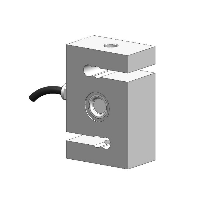

METRAVON MV-LC0094 is a metric-thread S-type load cell for axial tension and compression fixtures. Its dimensional table identifies 200, 300, 500, 1000, 2000, 3000 and 5000 kg versions. Specify the required rated capacity explicitly: a family range alone does not identify the thread, thickness or mounting envelope. Choose the actual version before designing the fixture around its end connections.
Read the metric-thread S-type load cell dimensions in both views
The front view uses H for height and L for front width; W is the body thickness in the side view. At 200 and 300 kg, H/W/L are 80/30/62 mm with M10 x 1 connections. The 500 kg row keeps those same dimensions but changes the thread to M12 x 1. Dimension letters are not interchangeable across other sensor families. Use this drawing to check the clevis opening, connection axis and available tool access.
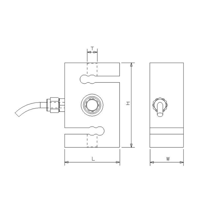
Compare the 1000 and 2000 kg sections before reusing the bracket
Both rows have H90 and L70 mm, but thickness W rises from 30 to 45 mm. The end designation also changes from M12 x 1 to M16 x 1.5. At 3000 kg the M16 x 1.5 designation remains while H/W/L increase to 100/50/80 mm. Sharing one thread size therefore does not preserve the surrounding envelope. Include the full motion of the external linkage so that a change in side clearance cannot become a changing force bypass.
| Item | Value | Selection notes |
|---|---|---|
| 200 / 300 kg H / W / L | 80 / 30 / 62 mm | Two M10 x 1 end connections are listed. |
| 500 kg H / W / L | 80 / 30 / 62 mm | The end thread changes to M12 x 1. |
| 1000 kg H / W / L | 90 / 30 / 70 mm | The thread remains M12 x 1. |
| 2000 kg H / W / L | 90 / 45 / 70 mm | Thickness increases and the thread becomes M16 x 1.5. |
| 3000 kg H / W / L | 100 / 50 / 80 mm | The M16 x 1.5 thread does not preserve the smaller body dimensions. |
| 5000 kg H / W / L | 130 / 58 / 92 mm | The end designation is M20 x 2. |
| Bridge input / output resistance | 380 / 350 ohms | The respective listed tolerances are +/-5 and +/-2 ohms. |
Identify the complete reference method for the test fixture
Define the operating force interval, direction, preload and the points used to decide whether a part passes. If a process also needs displacement or peak timing, specify those acquisition requirements in addition to this force bridge. Compare references through the intended metric fittings, not through a temporary adapter that is absent from production. A nominal 0.05% FS precision entry does not determine the entire fixture uncertainty or establish its dynamic recording performance.
Commission the bridge and verify the displayed quantity
The documented electrical interface uses 10-12 V DC excitation, with 2.0 +/-0.015 mV/V rated output. Confirm a suitable bridge reader rather than expecting a built-in current signal. Check the actual delivered wiring and load sign, then verify the indicated engineering units at the relevant force points. Keep the 200% FS safe load limit separate from accepted working loads and coupling strength. State the required enclosure version and connector exposure before relying on the listed IP67/IP68 options.
MV-LC0093 also lists a 500 kg M12 x 1 version, but with a 77 mm height and a different front width and thickness. Compare both drawings before changing families.
Actual ratings and section-view checks
Q1. Which capacity and connection should be stated on the enquiry?
State the required rated capacity, working force points and full thread at each end, and attach both fixture views. Use a matching dimensional row for the proposed version. For a rating outside the listed rows, request its own confirmed specification and drawing rather than estimating an intermediate body.
Q2. Can a 2000 kg body use the bracket from a 1000 kg assembly?
Height and front width match, but body thickness increases by 15 mm and the thread changes. Compare the side section, both fittings and the motion path. A retained bracket needs a full drawing review before calibration.
