


 Chinese
 Spanish
 Russian
 Portuguese
 French
 German
 Indonesian
 Thai
 Vietnamese
 Arabic
 Italian
 Turkish
 Polish
 Japanese



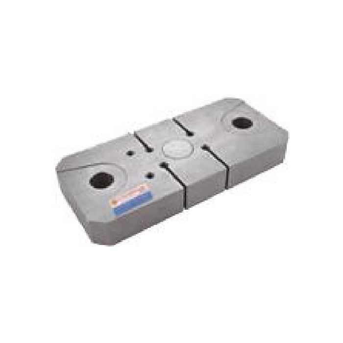
METRAVON MV-LC0091 is a plate-style tension load cell with a pin connection at each end. The model section gives a 5-20 t technical range and an illustrated 5/10 t outline, while another nearby technical entry gives 5-30 t. The exact ordered rating therefore needs matching capacity data and an installation drawing. Do not extend the illustrated body to a 20 t or 30 t application on the strength of a family range alone.
Identify the rated plate-style tension load cell before releasing the pins
Provide the existing label and both views of the installed link. Ask the quotation to identify a single rated configuration with its own pin bores, plate thickness, joint-centre distance and electrical specification. The reference outline marks the end bores as 2-D and the thickness as H/H1, but does not supply a complete numerical table for every capacity. Those missing values must come from a matched drawing; they cannot be calculated from the photograph or inferred from the 130 mm outer-height reference.
| Item | Value | Selection notes |
|---|---|---|
| Model-section range | 5-20 t | A nearby 5-30 t entry requires separate configuration confirmation. |
| Illustrated capacity labels | 5 / 10 t | Do not scale this outline to the other capacities. |
| End bores / thickness | 2-D / H and H1 | Request numeric values and tolerances for the selected unit. |
| Auxiliary thread reference | 2-M10 | Not a documented substitute for the two measuring joints. |
| Input / output resistance | 380 / 350 ohms | The listed tolerances are +/-10 and +/-5 ohms. |
| Precision / safe-load entries | 0.3% FS / 200% FS | Neither establishes an approved lifting or protective assembly. |
Keep auxiliary holes separate from the two measuring attachments
The drawing labels two M10 holes as well as the end bores. An auxiliary thread is not proof of an alternative force introduction point. Arrange the pulling members through the confirmed end connections and show any guard, anti-rotation feature or cable restraint for assessment. Leave the central cover and flexure slots clear during movement. A protective plate bearing against the measuring body can create a force bypass even though the assembly remains apparently secure.
Use the wider bridge-resistance tolerances stated for this model
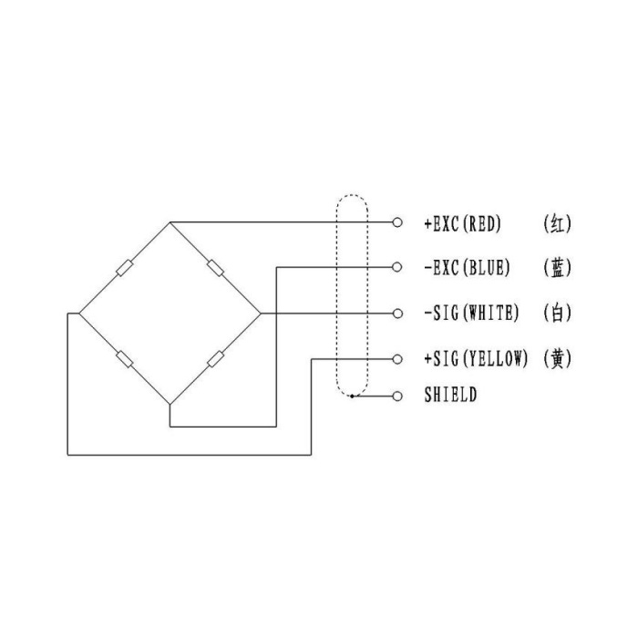
The electrical table lists 380 +/-10 ohms input resistance and 350 +/-5 ohms output resistance, with 2.0 +/-0.015 mV/V rated output and 10-12 V DC excitation. These tolerances differ from several nearby tension models. A resistance comparison must use the actual unit specification and the approved test method, not a borrowed limit. Establish the delivered wiring, force sign and calibration in the final reader before interpreting a different zero as a sensor fault.
Set force and motion checks for the assembled link
Specify normal tension, the smallest force change that matters and how the mechanism takes up slack. The documented precision is 0.3% FS; a dynamic process also needs an agreed recording method because no bandwidth or sample rate is established here. Compare repeated tensile references with the final pins and verify return after release. If a signal is intended to trigger a protective stop, assess that complete function separately; a sensor range and the 200% FS safe-load entry do not establish a safety-system approval.
Capacity release and attachment approval
Q1. Is a 30 t version confirmed by the existing range entry?
Not for procurement without its matching specification. The model section and nearby entry differ, and the shown outline is labelled 5/10 t. Obtain the actual 30 t configuration and drawing before approving a higher-range replacement.
Q2. Can the M10 holes carry the tensile load instead of the pins?
That is not established by the drawing. Keep the load through the documented end joints and submit any alternate attachment for technical review. A visible thread does not provide its permissible load, purpose or force-measurement conditions.
Q3. What makes the quotation ready for mechanical approval?
The offer should tie the selected capacity to a toleranced drawing, pin and bearing arrangement, bridge details and enclosure option. Include the planned force references and installation access. Separate the price of the sensing body from any pins, brackets or conditioning hardware that still need approval.
