


 Chinese
 Spanish
 Russian
 Portuguese
 French
 German
 Indonesian
 Thai
 Vietnamese
 Arabic
 Italian
 Turkish
 Polish
 Japanese



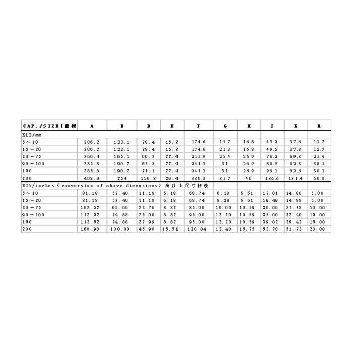
METRAVON MV-LC0084 is a profiled-body crane load cell documented for load sensing in cranes, gate hoists and related lifting equipment. The technical family is 5-250 klb. Its outer contour, central profile and end features must be matched to the actual load-introduction hardware. Do not turn the sensor family range into an assumed crane lifting capacity: the relationship between measured force and handled load depends on the approved mechanism.
Identify the crane load cell by its contact geometry
Provide front and side views of the existing sensor and the parts that contact it. The reference drawing distinguishes the overall A dimension, longitudinal B reference, D section and additional end and contour features. Identify which features locate the body, which transfer force and how unintended movement is restrained. Neither a centre contour nor an end opening defines a complete installed force path by itself. An existing mounting arrangement requires a matched assembly review rather than a comparison of overall length alone.
Preserve klb capacity units while comparing metric dimensions
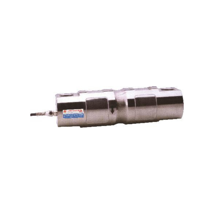
In the metric outline table, the 5-10 and 15-20 klb groups share A206.2, B133.1 and D28.4 mm, but their G references differ at 15.7 and 21.3 mm. At 90-100 klb and 150 klb, A285.8 and B190.2 mm match while D increases from 63.5 to 71.1 mm. Check the complete row even when two major dimensions agree. The displayed dimensional rows stop at 200 klb; a 250 klb order needs its own confirmed outline rather than an extrapolation.
| Item | Value | Selection notes |
|---|---|---|
| 5-10 klb A / B / D | 206.2 / 133.1 / 28.4 mm | The G reference is 15.7 mm. |
| 15-20 klb A / B / D | 206.2 / 133.1 / 28.4 mm | G changes to 21.3 mm despite matching main dimensions. |
| 90-100 klb D | 63.5 mm | Use the full profiled-body row with its mating contact parts. |
| 150 klb D | 71.1 mm | The shared A/B references do not preserve the section. |
| 250 klb configuration | Matching outline required | No 250 klb dimensional row is supplied in this reference table. |
| Bridge / excitation | 2.0 mV/V / 10-12 V DC | The output tolerance is +/-0.01 mV/V. |
Separate the load measurement from the crane control decision
State whether the signal is used for an indication, a recorded operating value or a protective action. Describe the mechanism configurations that change the relationship between sensor force and handled load. The documented 200% FS safe-load entry is a sensor limit, not an approved working load for the crane or a basis for selecting a trip threshold. No response time, safety integrity or complete protective-system certification is established by the sensor specification.
Connect and test the bridge through the final acquisition chain
The output is 2.0 +/-0.01 mV/V with 10-12 V DC excitation; input and output resistances are 750 +/-20 and 700 +/-5 ohms. Choose the indicator or conditioner to match those values and record where the conversion to the displayed load is applied. Use confirmed delivered wiring, then verify direction and known reference conditions with the final mounting hardware. The 0.05% FS precision entry does not remove errors in the mechanism model or establish a finished crane load indication.
Include service conditions in the purchase scope
Record cable movement, access for inspection, ambient temperature and exposure to rain, wash water or standing water at the termination. The temperature entry is -40 to +85 deg C, and enclosure protection must be confirmed for the actual delivered configuration. Ask the offer to distinguish the sensing body, mating hardware, connector and any signal electronics. A welded body is not evidence that all external connections have the same environmental or load rating.
If the retained hardware instead uses the rectangular end-hole arrangement, review MV-LC0085 joint geometry. The two body layouts need separate contact and rated-drawing checks, even where their nominal bridge specifications agree.
Capacity units and machine integration
Q1. Does a 100 klb sensor mean the crane may lift 100 klb?
No. The sensor capacity applies to its specified force, not automatically to the handled load. Establish the mechanism relationship and the permitted machine conditions through the appropriate engineering assessment.
Q2. Can the 15-20 klb version use hardware from the 5-10 klb group?
The main A/B/D values match, but another contour reference changes. Compare every relevant mating surface and locating feature on a matched drawing. Similar outer dimensions cannot approve retained contact parts.
Q3. What is needed when the load signal triggers a stop?
Specify the complete intended function, controller input, response requirement and applicable machine procedure. The sensing element is only part of that chain. Do not treat its overload percentage or static precision figure as a safety approval.
