


 Chinese
 Spanish
 Russian
 Portuguese
 French
 German
 Indonesian
 Thai
 Vietnamese
 Arabic
 Italian
 Turkish
 Polish
 Japanese


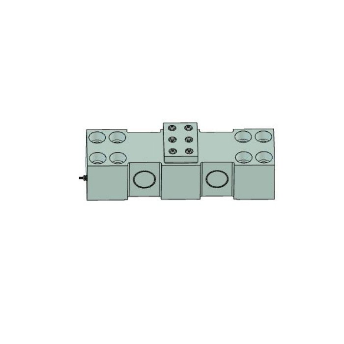

METRAVON MV-LC0083 is a high-capacity bearing block load cell with a raised central attachment and eight end-fixing references. The dimensional table identifies 50, 100, 150 and 200 t rows, while the nominal-range line elsewhere is malformed and does not define a reliable ordered range. Confirm the selected rating against a matching specification. Its listed 1.5 mV/V output is also different from nearby 2 mV/V bearing sensors and needs the correct reader calibration.
Match the central seat on the high-capacity bearing block load cell
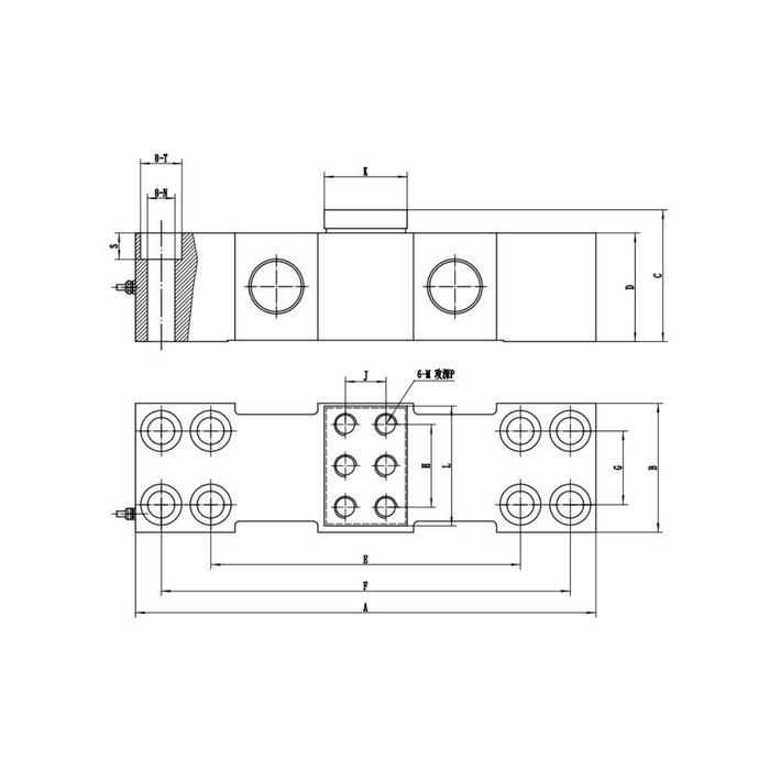
The drawing separates eight end-fixing positions from a six-hole central attachment. The central M designation is M20 in the 50 t row and M24 at 100, 150 and 200 t; the table does not state the thread pitch. Identify all six bearing-attachment positions and their engagement before reusing a housing or adapter. A shared M24 designation at several capacities does not preserve the seat dimensions, support spacing or full outer envelope.
Compare the base footprint across the reference rows
Overall A grows from 450 mm at 50 t to 500, 560 and 620 mm at 100, 150 and 200 t. The longitudinal F reference changes from 398 to 444, 500 and 560 mm respectively. Base width B is 120, 140, 160 and 180 mm across those rows. Use the exact drawing to locate the end bolts and identify the supporting faces. Do not reuse a shorter base by omitting outer fixings or supporting a measuring region that was intended to remain free.
| Item | Value | Selection notes |
|---|---|---|
| 50 t A / F / B | 450 / 398 / 120 mm | Central thread reference is M20; confirm pitch. |
| 100 t A / F / B | 500 / 444 / 140 mm | The central attachment changes to M24. |
| 150 t A / F / B | 560 / 500 / 160 mm | M24 alone does not identify the whole seat pattern. |
| 200 t A / F / B | 620 / 560 / 180 mm | Check the larger base and all end-fixing positions. |
| Listed bridge sensitivity | 1.5 +/-0.01 mV/V | Do not retain a 2 mV/V scale without recalibration. |
| Range release | Rated specification required | Drawing rows are references, not a corrected nominal-range statement. |
Correct the bridge scale when changing from a 2 mV/V channel
The electrical entry is 1.5 +/-0.01 mV/V at 10-12 V DC excitation, with 750 +/-20 ohms input and 700 +/-5 ohms output resistance. At rated load and a 10 V excitation, nominal bridge output is therefore 15 mV; this is a calculated signal example, not a separate supply or a tolerance limit. A reader left at a 2 mV/V full-scale setting will use the wrong conversion. Confirm actual excitation, delivered sensitivity and the required force units before setting the final channel scale.
Allow for shaft alignment and service access in the assembly review
A high-capacity housing installation needs more than the load-cell footprint. Show the bearing position, shaft centre, adjacent support, lifting or removal access and the route to the cable termination. Include any restraints or guards that can touch the sensing body after assembly. The stated -40 to +85 deg C temperature range and IP67/IP68 family entry do not automatically cover the bearings, end fasteners or junction enclosure; specify their real operating exposure separately.
Release the rating and reference-load method together
The malformed range line cannot be repaired by guessing what it was intended to say. Obtain a specification that identifies the offered rating and confirms the matching dimensional row. Then agree how reference reaction is applied through the central seat and how repeatability and return are checked with the installed housing. The 0.05% FS precision entry does not include unknown bearing friction, fixture distortion or a payload calculation. Acceptance should state the required installed result rather than simply repeat that sensor figure.
Rated versions, adapters and reader settings
Q1. Does the table confirm that any capacity between 50 and 200 t is offered?
It identifies four dimensional reference rows, not every intermediate rating. The malformed nominal-range entry needs a corrected specification for the actual offered version. Obtain that confirmation before accepting a capacity on the order.
Q2. Will a reader designed for 2 mV/V necessarily need replacement?
Not necessarily. Check its permitted bridge range, excitation and calibration facilities against the 1.5 mV/V unit. A suitable reader may be reconfigured and recalibrated, but matching connectors or the same resistance does not establish that capability.
Q3. Can the same M24 adapter be retained for all larger versions?
Only after reviewing the complete seat pattern, engagement, reaction and surrounding geometry. The shared thread label does not make the 100, 150 and 200 t bodies mechanically interchangeable. Confirm the approved assembly rather than transferring an adapter by its thread size alone.
