


 Chinese
 Spanish
 Russian
 Portuguese
 French
 German
 Indonesian
 Thai
 Vietnamese
 Arabic
 Italian
 Turkish
 Polish
 Japanese



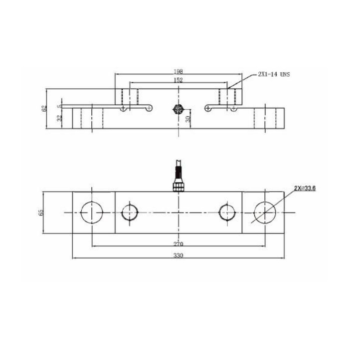
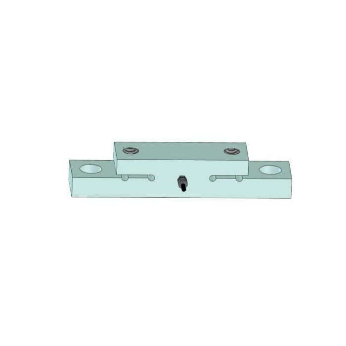
The METRAVON MV-LC0082 pillow block load cell measures the reaction transmitted by a bearing housing. Its two ends attach to the base while the housing loads the raised central section. The specified measuring range is 0-5.67 t, with a nominal 0.5 mV/V bridge output. Select it from the bearing reaction and mounting arrangement, not from the total machine weight alone.
Keep the bearing load in the sensing path
This structure uses shear strain in the sections between the central loading area and the fixed ends. A support, shim or housing contact that bridges those sections can carry part of the load around the sensor. Check the underside clearance, bearing fasteners and base flatness before choosing the capacity.
For a shaft supported at two bearings, the reaction at each bearing depends on where the external force acts. It need not be half the total force. Submit the bearing spacing, force location and expected dynamic loads so that the most heavily loaded support can be assessed. Where the measurement is used for a crane overload alarm, the sensor remains one component of the system; alarm logic and the machine's safety functions require their own validation.
Pillow block load cell mounting and electrical data
| Item | Specified value | Use in selection |
|---|---|---|
| Measuring range | 0-5.67 t | Assess the peak reaction at this bearing, including the load already present before zeroing. |
| Rated output | 0.5 ± 0.01 mV/V | The amplifier must resolve this lower bridge signal over the required working range. |
| Excitation | 10-12 VDC | Check the instrument's bridge supply rather than its external power supply. |
| Input / output resistance | 400 ± 20 / 350 ± 5 ohms | Check excitation loading and the input circuit before connecting several sensors. |
| Combined accuracy | 0.5% FS | This sensor specification does not establish the installed machine's measurement uncertainty. |
| Operating temperature | -40 to +85 °C | Include bearing heat in the assessment, not only the surrounding air temperature. |
| Safe overload | 200% FS | Keep normal and expected dynamic loads within the rated measuring range. |
The outline drawing gives a 330 mm overall length, 270 mm end-hole centre spacing and 65 mm width. These dimensions help screen the available space; the central fixing arrangement and bearing interface still need the full drawing. Alloy-steel and stainless-steel versions, and IP67/IP68 protection options, must be identified separately in the quotation.
Match the amplifier to a 0.5 mV/V bridge
At 10 V excitation, the nominal full-scale signal is 5 mV, calculated as 0.5 mV/V multiplied by 10 V. An input configured for a different sensitivity may display a reading but use the wrong scale factor. Specify the amplifier input range, noise performance and calibration method before replacing a sensor in an existing system.
A PLC voltage or current input cannot replace the bridge excitation and millivolt measurement circuit. Choose a compatible weighing instrument or signal conditioner, then confirm any required 4-20 mA or RS485 interface on that device.
Questions about installation and commissioning
Q1. Will the reading equal the suspended load on a crane?
Not necessarily. The bearing reaction can include the drum assembly's weight and forces produced by the rope arrangement. Establish the relationship between the measured reaction and the required load indication, then calibrate the assembled system with an approved procedure. Do not treat the sensor reading as a direct hook-load value without that assessment.
Q2. What should be checked if zero changes after the bearing bolts are tightened?
Inspect base flatness, contact under the central section and any housing distortion introduced by tightening. Compare readings through the specified assembly sequence. Do not conceal a mechanically induced change by repeatedly resetting zero before checking whether the load path is correct.
Q3. How should a replacement be accepted?
Record the installed zero, apply known loads at representative operating positions, unload and repeat. Compare both the indicated load and the return to zero. Agree the allowable error for the complete machine beforehand; the 0.5% FS sensor figure is not an automatic acceptance limit for the installation.
For an MV-LC0082 quotation, send the bearing and base drawings, calculated reactions, loading cycle, available bridge instrument and exposure to heat or water. Include photographs showing the underside of the bearing housing so that unintended contact can be identified.
