


 Chinese
 Spanish
 Russian
 Portuguese
 French
 German
 Indonesian
 Thai
 Vietnamese
 Arabic
 Italian
 Turkish
 Polish
 Japanese


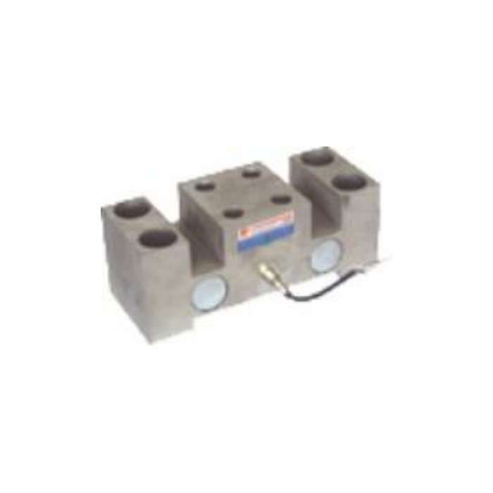

METRAVON MV-LC0081 is a bearing block load cell intended to measure the reaction beneath a bearing housing. Its technical entry states 10-50 t, but the accompanying dimensional table lists 1.5, 2.5, 4 and 10 t and uses dimension letters that do not fully match the illustrated body. Treat the drawing as an identification reference until the actual rated version and its dimensions are confirmed. It is not sufficient information for machining a replacement base.
Resolve the bearing block load cell drawing before placing the mechanical order
The outline identifies an elevated central bearing seat, two end-support regions, four central attachment holes and separate end fixings. The table alongside it does not supply a consistent dimensional definition for all of those features over the stated capacity range. Request one approved drawing showing the selected rating, all hole centres and diameters, counterbores, seat height and cable exit. Even the shared 10 t label is not enough to link a mismatched set of dimension letters to the correct body.
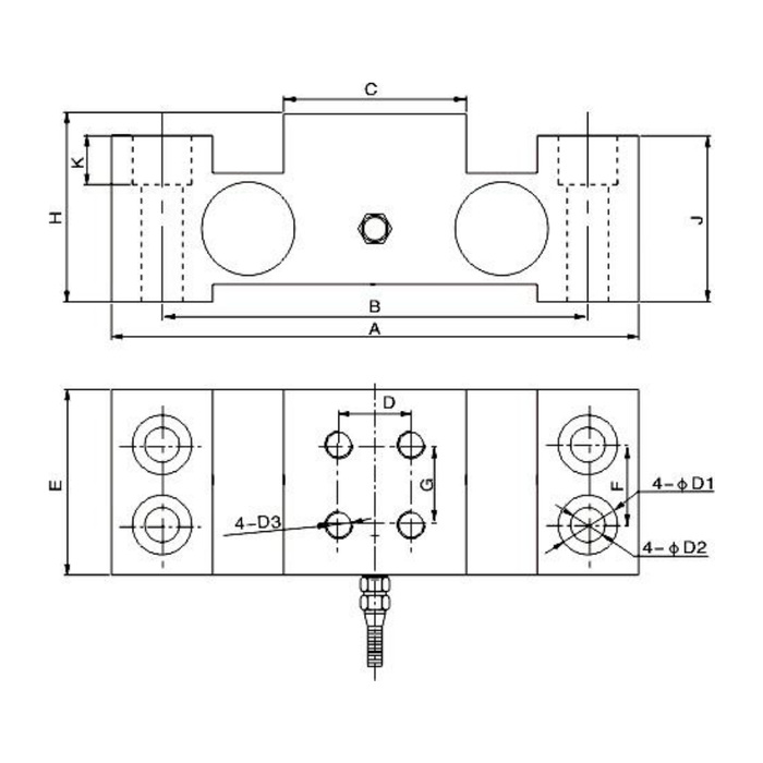
Distinguish housing location from base restraint
In the described arrangement, the bearing housing attaches at the central region and the sensor ends are fixed to the base. Show how the bearing position is established and which parts resist lateral movement. Do not add a clamp over the central seat, enlarge a fixing hole or use the circular side covers as locating faces to adapt an unmatched replacement. The assembled shaft alignment and intended measuring deformation both need to be retained; fitting bolts alone does not establish that result.
| Item | Value | Selection notes |
|---|---|---|
| Technical capacity entry | 10-50 t | Requires dimensions tied to the actual offered rating. |
| Dimensional-table ratings | 1.5 / 2.5 / 4 / 10 t | Not a complete mounting definition for the 10-50 t entry. |
| Central seat / end supports | Separate attachment regions | The actual hole centres, counterbores and heights need confirmation. |
| Bridge sensitivity / excitation | 2.0 mV/V / 10-12 V DC | The listed sensitivity tolerance is +/-0.01 mV/V. |
| Input / output resistance | 750 / 700 ohms | Tolerances are +/-20 and +/-5 ohms respectively. |
| Listed precision | 0.02% FS | Set bearing-reaction acceptance points for the finished installation. |
Review the required reaction resolution against the listed bridge data
The reference precision entry is 0.02% FS, with 0.02% FS per 10 deg C temperature effect. These are sensor entries, not a verified error for a bearing system or a computed payload. Define the reaction interval and allowable error at the working points before selecting a rating. The listed electrical channel is 2.0 +/-0.01 mV/V with 10-12 V DC excitation; its 750 +/-20 ohm input and 700 +/-5 ohm output require a suitable bridge reader, not an assumed direct current-loop connection.
Make the quotation identify both the records and the delivered scope
Provide housing and shaft drawings, expected bearing reactions, the old label and the existing indicator details. Ask for the matched dimensional release, electrical specification, installation requirements and selected enclosure configuration in the response. The offer should also state whether it includes only the sensor or any interface parts. Until those records agree, keep the base fabrication and retained-fastener approval open rather than accepting a nominal range as a complete mechanical specification.
Use acceptance to check the actual installation, not to guess the missing drawing
Once the rated configuration and installation are approved, compare known reference conditions with the final bearing housing secured and the shaft aligned. Observe repeatability, empty return and changes after an allowed alignment adjustment. A stable zero cannot confirm that the right body was supplied or that an undocumented bolt pattern is suitable. If the result feeds a protection system, its thresholds, response and fault behaviour remain a separate system-level verification.
Questions to resolve before base fabrication
Q1. Can the 10 t row be used because it overlaps the technical range?
Not without confirmation. The table and drawing use inconsistent feature definitions, so a shared capacity label alone cannot establish the hole pattern or seat geometry. Obtain a matched drawing for that exact version before machining or approving a retained base.
Q2. What can be checked while the correct drawing is being obtained?
Collect the installed label, bearing housing pattern, shaft centre height, end-support geometry, cable route and bridge-reader settings. These observations support the replacement review, but they do not replace the rated product drawing or establish compatibility. Keep dimensional approval separate from the initial enquiry.
