


 Chinese
 Spanish
 Russian
 Portuguese
 French
 German
 Indonesian
 Thai
 Vietnamese
 Arabic
 Italian
 Turkish
 Polish
 Japanese


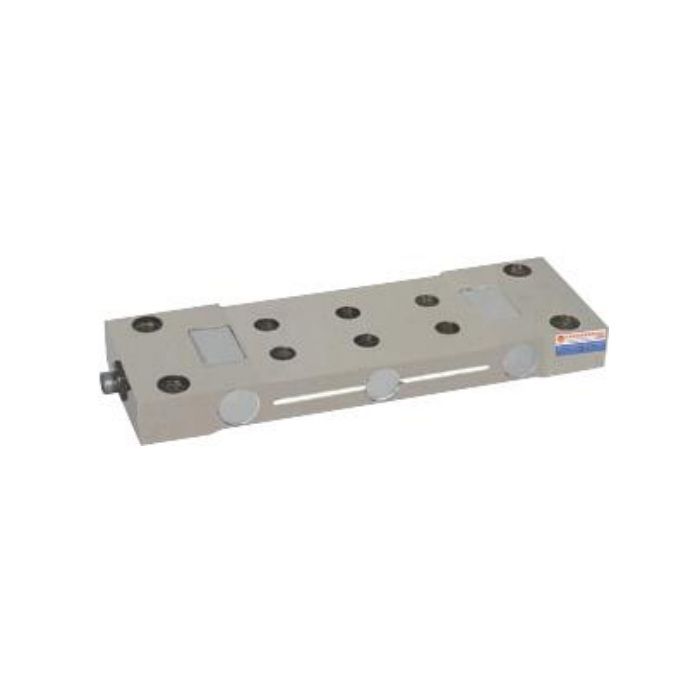

METRAVON MV-LC0080 is a pillow block load cell installed beneath a bearing housing to measure its support reaction. The housing loads the central region, and the two ends attach to the base. Its 1.5-10 t reference family includes different bearing-hole layouts even where the overall body size stays unchanged. For a retrofit, match the bearing attachment and the base attachment separately before accepting the mechanical fit.
Compare the two fixing patterns on the pillow block load cell
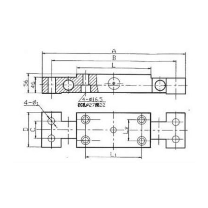
The 1.5 t metric row gives overall reference A350 mm, end-fixing reference B310 mm and central references L152 and L1 100 mm. At 2.5 t, A/B become 410/355 mm and L/L1 become 182/130 mm. The 4 t and 10 t rows retain A410 and B355 but use L212 and L1 160 mm. Matching only the outside length or end-bolt spacing can therefore leave the bearing holes in the wrong position. Check the complete top and side views with the actual housing.
| Item | Value | Selection notes |
|---|---|---|
| 1.5 t A / B | 350 / 310 mm | Central L/L1 references are 152/100 mm. |
| 2.5 t A / B | 410 / 355 mm | The central pattern uses L182 and L1 130 mm. |
| 4 t / 10 t A / B | 410 / 355 mm | L212 and L1 160 differ from the 2.5 t central pattern. |
| End-hole reference, 1.5 / 2.5-10 t | 17 / 21 mm | Confirm hole fits and fasteners from the approved assembly. |
| Operating temperature | -40 to +85 deg C | Evaluate the housing, cable termination and reader as well. |
| Temperature-effect entry | 0.02% FS per 10 deg C | Use the actual useful-force and temperature requirements at acceptance. |
Keep the bearing reaction inside the intended measuring path
The bearing housing must transmit its load through the central attachment to the sensor and then through the two supported ends. Show any shims, alignment keys, retaining brackets and nearby steel in the assembly drawing. A stiff plate bridging the sensing section or a housing touching an adjacent support can carry force outside that path. Check the shaft centre height and alignment after adding the sensor; a body that fits the bolt holes can still alter the bearing arrangement.
Select from the bearing reaction, not the suspended payload alone
Provide the bearing and shaft layout, supported masses and the forces acting at the measured support. Where ropes, drums or sheaves load the shaft, their geometry and operating condition affect the reaction. Do not divide a crane payload by the number of bearings and assume that is the sensor load. The proposed rating needs a reaction assessment for the actual mechanism, including start, stop and other project-defined events. No universal dynamic multiplier is specified here.
Read the bridge as a force channel before using it as an alarm input
The documented values are 10-12 V DC excitation, 2.0 +/-0.01 mV/V rated output, 750 +/-20 ohms input resistance and 700 +/-5 ohms output resistance. A bridge conditioner or indicator must provide excitation and the required engineering-unit conversion. If a PLC receives a subsequent current signal, identify that separate output stage on the quotation. Request the delivered wiring and verify the loaded sign instead of choosing signal colours from conflicting reference labels.
Validate the installed housing and the final indicated quantity
The listed precision is 0.05% FS, not a guarantee for the entire shaft, bearing and calculation chain. Compare controlled reference conditions after the final housing alignment and fastener arrangement are approved. Check zero return, repeat readings and whether housing adjustment changes the result. If the channel is used in an overload alarm, test that complete function under an approved procedure; a sensor safe-load entry does not establish the alarm setting or system safety performance.
For a raised bearing seat rather than this flat attachment layout, compare the MV-LC0081 mounting outline. Its dimensional records still require confirmation, so it is not an approved drop-in alternative.
Bearing attachments and the measured force
Q1. Can the 2.5 t body be replaced by the 4 t version without changing the housing?
The outer A/B references match, but the central L/L1 dimensions change from 182/130 to 212/160 mm. Compare the bearing attachment rather than approving the replacement from its overall length. The force range and calibration also need review.
Q2. Does measuring one bearing give the hook load directly?
It gives that measured support reaction. Converting it to hook load requires the actual mechanism and an established relationship under the relevant operating conditions. Identify changing rope geometry or other support loads before deciding what the display should represent.
Q3. May a base shim touch the whole underside?
Use the support arrangement approved for the sensor. A shim or plate that bridges a region intended to deform can change the measurement. Submit the base and shim section for review rather than copying the bearing-housing footprint onto the entire sensing body.
