


 Chinese
 Spanish
 Russian
 Portuguese
 French
 German
 Indonesian
 Thai
 Vietnamese
 Arabic
 Italian
 Turkish
 Polish
 Japanese



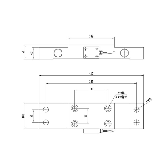
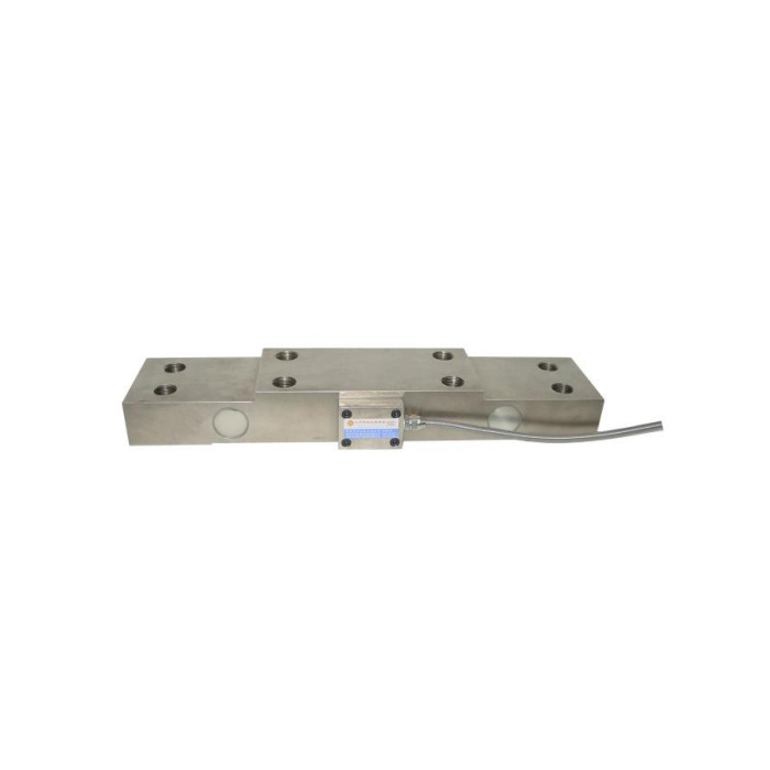
METRAVON MV-LC0079 is a pillow block load cell for measuring the support reaction beneath a bearing housing. The bearing loads the central section while the sensor's two ends are fixed to the base. Its listed capacity range is 1.5-30 t, but selection starts with the bearing reaction and mounting arrangement, not the total weight of the machine.
Follow the force from the bearing into the base
The sensing body uses shear deformation between the central loading area and the end supports. A correctly arranged installation sends the intended bearing load through those sections. Contact beneath a section intended to deflect, or an added support that bypasses the sensor, can change the relationship between the applied force and the output.
Review the complete bearing assembly for vertical, lateral and axial reactions. Identify the force component to be measured and how the other loads are restrained. Do not assume the sensor measures every component of shaft load or that one bearing reaction equals the entire suspended load.
| Installation detail | What must be established |
|---|---|
| Bearing attachment | Locate the bearing on the intended central mounting region and check its bolt pattern. |
| End supports | Match the base fixings and support surfaces to the selected capacity drawing. |
| Load calculation | Determine the maximum local bearing reaction, including the relevant operating cases. |
| Clearance | Check that guards, stops and adjacent structure cannot create an unintended parallel load path. |
Ratings and instrument compatibility
| Parameter | MV-LC0079 |
|---|---|
| Capacity range | 1.5-30 t |
| Rated signal | 2.0 +/-0.01 mV/V |
| Bridge excitation | 10-12 V DC |
| Input resistance | 400 +/-20 ohm |
| Output resistance | 350 +/-5 ohm |
| Catalogue accuracy figure | 0.1% of full scale |
| Operating temperature | -40 to +85 deg C |
| Ingress protection | IP67 |
| Safe load limit | 200% of full scale |
Dimensions vary with capacity. The catalogue contains multiple mounting sizes, so a drawing for one rating is not sufficient evidence for another. Confirm the selected capacity, material and detailed drawing in the quotation; alloy steel and stainless steel are listed material alternatives.
Use a bridge-compatible instrument to excite and read the sensor. If the result is needed by a PLC, RTU or data logger, define the conditioning and output stage separately. The sensor's mV/V rating is not an integrated 4-20 mA or digital communication interface.
Bearing-load questions
Q1. Can the reading be converted directly into rope tension?
Only after the mechanism's force relationship has been established. Bearing reaction can depend on rope direction, reeving, supported dead load and load sharing. Have the machine designer define that relationship and verify it against known operating loads; do not assume a universal one-to-one conversion.
Q2. Does fitting this sensor create an approved overload-protection system?
The sensor supplies a measurement, not approval of the complete protective function. Alarm thresholds, fault detection, control response and machine acceptance need a separately engineered system. The catalogue overload limit must not be used as the machine's operating threshold.
For an MV-LC0079 application review, provide the bearing and base drawings, calculated reactions, expected transient loads and required output. Include the planned calibration method and whether the measurement is for monitoring or part of a protective function, so the quotation addresses the actual system responsibility.
