


 Chinese
 Spanish
 Russian
 Portuguese
 French
 German
 Indonesian
 Thai
 Vietnamese
 Arabic
 Italian
 Turkish
 Polish
 Japanese


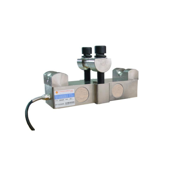

METRAVON MV-LC0078 is a clamp-on wire rope tension sensor, not a general load cell for a weighbridge deck. The described assembly secures a rope at the end grooves and uses a central guide arrangement to transfer a force related to rope tension into the bridge body. Its detailed technical entry is 1-10 t, while a larger drawing group and a reference photograph extend beyond that entry. Confirm the actual rated assembly and rope fit instead of treating every reference image as an offered version.
Select the wire rope tension sensor from both rope and force requirements
Provide rope diameter, construction, working tension, the intended rope segment and whether that segment moves relative to the proposed clamp. Diameter alone does not establish a calibrated tension installation. The sensor measures the reaction produced by its particular rope geometry; the displayed rope tension needs the correct installed relationship. Do not assume that it can be fitted where rope continuously travels through a clamped section. That location and the permitted contact arrangement need approval for the actual equipment.
Use the dimensional groups without extending the offered capacity
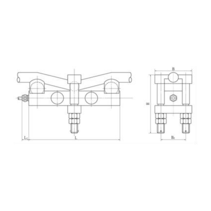
The 1-2 t reference row shows rope diameters 6-14 mm, H117 mm and L160 mm. The 3-5 t row shows 16-26 mm rope, H170 and L260 mm. A further 10-30 t drawing row shows 24-36 mm rope, H175 and L272 mm, but the technical range is only 1-10 t. For a proposed 10 t version, obtain a matching rated specification and rope configuration; do not read the drawing as confirmation of every capacity up to 30 t or every rope within an overlapping diameter interval.
| Item | Value | Selection notes |
|---|---|---|
| 1-2 t reference rope / H / L | 6-14 / 117 / 160 mm | Confirm the rated configuration and actual rope construction. |
| 3-5 t reference rope / H / L | 16-26 / 170 / 260 mm | A different rope or clamp setting needs calibration review. |
| Higher outline group | 10-30 t drawing reference | Not confirmation of a capacity beyond the 1-10 t technical entry. |
| Input / output resistance | 400 / 350 ohms | Listed tolerances are +/-20 and +/-5 ohms. |
| Output / excitation | 2.0 mV/V / 10-12 V DC | Sensitivity tolerance is +/-0.01 mV/V. |
| Required installed record | Rope / clamp / reference tension | A body calibration alone does not define every rope installation. |
Keep the clamp, guide and rope condition in the calibration record
Request the approved clamp parts, guide contact and assembly instructions for the actual rope. No universal bolt torque, permissible rope deformation or correction coefficient is established by this reference. Record the rope and final geometry when establishing the indicated tension. If the rope type, guide position or clamping arrangement changes, review the calibration rather than retaining an old span because the sensing body is unchanged. Inspect the relevant rope contact under the equipment-approved maintenance procedure.
Choose the electrical channel for this tension assembly
The bridge requires 10-12 V DC excitation and has 2.0 +/-0.01 mV/V rated output. Input and output resistances are 400 +/-20 and 350 +/-5 ohms, not the 750/700-ohm values used by some neighbouring weighing supports. The sensor does not establish a built-in current or digital-bus interface. Specify a compatible indicator or conditioner and confirm delivered terminal identity before a controlled sign and reference-tension check. A circuit that powers up correctly is not evidence that the rope-tension conversion is calibrated.
Verify the indicated tension and any alarm as separate functions
The listed precision is 0.05% FS for the sensor entry; it is not a verified accuracy for every rope construction and clamp condition. Agree installed reference tensions and repeat checks over the useful range. If a controller uses that reading for an alarm or a stop, validate the complete intended function under the machine procedure. The 200% FS safe-load entry does not approve a lifting load, establish a trip point or justify an overload test on the rope assembly.
Rope-specific calibration and rated versions
Q1. Why does a reference photo show 30 t when the technical entry says 1-10 t?
The reference material is not one matched rated configuration. The image and wider outline cannot approve a 30 t order under the stated technical entry. Request the actual unit label, capacity data and rope-specific assembly drawing before selection.
Q2. Can one diameter setting be used for every rope of that nominal size?
Not as a confirmed calibration. Rope construction, condition and the installed geometry affect the relationship that is being measured. Provide the actual rope specification and establish the required tension references with the approved assembly.
Q3. Is a 2 mV/V indicator enough to measure rope tension correctly?
It may read the bridge, but it does not supply the missing installed tension conversion. Match excitation and bridge loading, then calibrate the complete rope-sensor arrangement. Confirm any subsequent output to the controller separately.
Q4. What should the enquiry include besides the desired capacity?
Send rope construction and diameter, working tensions, location photos, available space, relative rope movement and the required display or control input. Identify whether the request is for indication or a protective function. Ask for matched capacity data and the approved clamp arrangement in the offer.
