


 Chinese
 Spanish
 Russian
 Portuguese
 French
 German
 Indonesian
 Thai
 Vietnamese
 Arabic
 Italian
 Turkish
 Polish
 Japanese


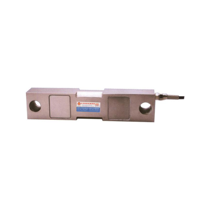

METRAVON MV-LC0085 is a rectangular crane load cell with end-hole references for its mating connections. Its technical family is 5-250 klb, but the hole spacing and body cross-section vary across the dimensional groups. For a replacement, define the exact rated unit and the complete pin or attachment arrangement. The same centre spacing at two capacities does not demonstrate that the existing surrounding hardware can be retained.
Measure the rectangular crane load cell in section as well as length
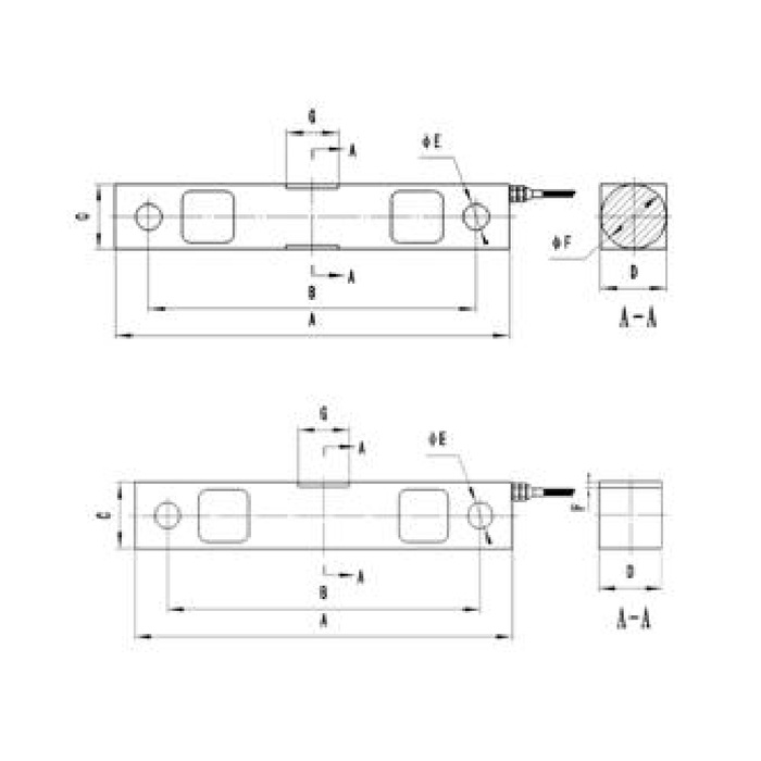
The 10-25 klb metric group lists A222.3 mm overall, B190.5 mm between the end-hole references and E20.6 mm bore diameter. At 35 klb those values remain, while section references C/D change from 49.3/36.6 to 63.5/38.1 mm. A pin may therefore line up while the thicker or taller body interferes with the adjoining structure. Include both section views and the motion of the connected members, not just a ruler measurement between the holes.
| Item | Value | Selection notes |
|---|---|---|
| 10-25 klb A / B / E | 222.3 / 190.5 / 20.6 mm | C/D section references are 49.3/36.6 mm. |
| 35 klb A / B / E | 222.3 / 190.5 / 20.6 mm | C/D change to 63.5/38.1 mm. |
| 50 / 75 klb A / B / E | 342.9 / 292.1 / 33.3 mm | Other section and interface details still need the selected drawing. |
| Listed precision | 0.05% FS | Define the installed machine checks independently of this sensor entry. |
| Temperature-effect entry | 0.02% FS per 10 deg C | Assess its significance at the useful measured load. |
| Ordered version | Capacity and drawing revision | Do not extrapolate a 250 klb layout or use outside-family outline rows. |
Do not transfer an uncertain table value into the pin design
The 50 and 75 klb rows give A342.9, B292.1 and E33.3 mm. Other entries in the reference table are not a reliable basis for every section or offered capacity: the technical family extends to 250 klb, the outline list also includes outside-family rows, and some section entries require clarification. Request a complete toleranced drawing for the selected rating. Use neither the incorrect imperial conversion rows nor an adjacent capacity to fill a missing pin, section or clearance value.
Review the joint and retained hardware as a complete assembly
Identify pin material and condition, bearing length, mating lug or clevis width, retention and the permitted articulation. Those are project requirements to assess, not properties established by the sensor bore diameter. Show restraints and any covers that could touch the measuring body during movement. Do not ream a hole or add an unreviewed bushing to solve a mismatch. Approval of the mechanical connection should precede calibration, rather than rely on a plausible display after assembly.
Verify the bridge channel without changing mechanical limits
The electrical specification is 2.0 +/-0.01 mV/V, 10-12 V DC excitation, 750 +/-20 ohms input resistance and 700 +/-5 ohms output resistance. Confirm the delivered terminal identity and loaded sign with an appropriate reference method. If an existing indicator is retained, check its bridge settings and the conversion to the intended indicated quantity. Software scaling cannot increase a pin rating, approve a different load direction or correct a joint that binds under load.
Agree the replacement evidence and acceptance before shutdown
The quotation should name the exact rated version, drawing revision, interface parts, cable termination and required signal conditioning. Plan access to remove and inspect the connections, together with the machine-approved reference-load checks after reassembly. The stated precision is 0.05% FS, and the safe-load entry is 200% FS; neither defines the finished machine acceptance tolerance or authorises an overload test at that percentage. Confirm the actual test method and operating constraints separately.
Pinned-joint replacement questions
Q1. Can matching hole spacing establish that a replacement will fit?
It establishes only one geometric reference. Compare the bore, section dimensions, adjacent hardware and required movement as well. The 10-25 and 35 klb groups illustrate why the same spacing can accompany a different body section.
Q2. Does the diameter specify which pin is strong enough?
No. It does not define the pin material, bearing condition, load distribution or the strength of the adjacent lugs. The complete joint needs assessment for its actual force and operating conditions.
Q3. May a 300 klb outline be ordered under the stated family?
The technical family is 5-250 klb, so an outside-family outline is not confirmation of that rating. Obtain a matching technical specification and offered configuration instead of treating every drawing row as an available product.
Q4. What should an initial replacement enquiry include?
Provide the old label, operating force requirements, both joint sections, measured space, existing indicator and cable route. Ask for a matched rated drawing and identify any pins, connectors or conditioners to be included. This allows the offer to separate confirmed items from unresolved interfaces.
