


 Chinese
 Spanish
 Russian
 Portuguese
 French
 German
 Indonesian
 Thai
 Vietnamese
 Arabic
 Italian
 Turkish
 Polish
 Japanese


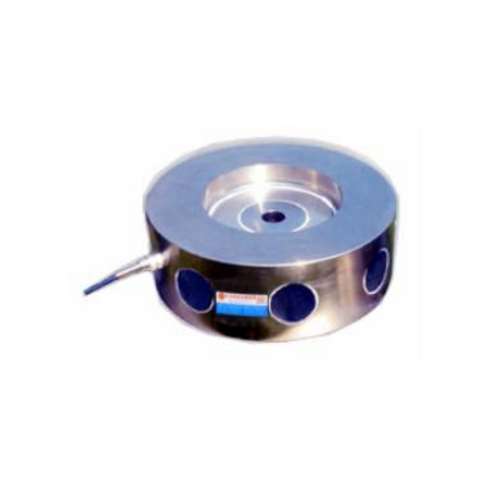

METRAVON MV-LC0037 is a high-capacity compression load cell with a published 100-350 t technical range. Its reference drawing shows a circular sensing body on a square base, so a purchase enquiry needs more than the nominal tonnage. The upper bearing part, foundation support and supplied base arrangement determine whether the assembly can transmit the intended force. Specify the maximum compression at each support and identify the bearing parts retained in the installation.
Review the complete bearing assembly before fixing the foundation
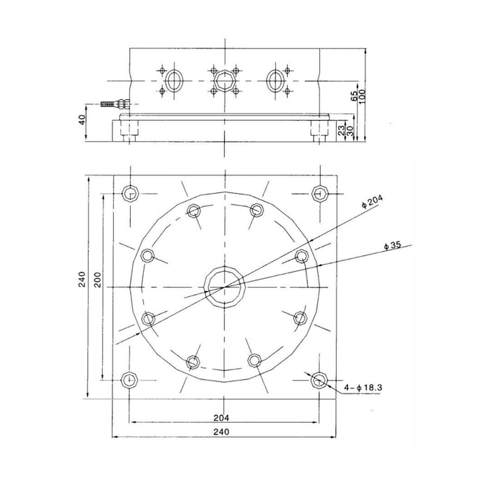
The outline shows a 240 by 240 mm base, four diameter-18.3 mounting positions and a 204 mm horizontal centre spacing. The vertical hole spacing is labelled 200 mm, not the same 204 mm value. A circular diameter-204 callout also appears on the body. These similar numbers describe different features and should not be merged into a square bolt pattern. Ask for a dimensioned base plan and the selected rated section before drilling, especially where an existing foundation is to remain.
Distinguish the high-capacity compression load cell from its mounting parts
The illustrated assembly carries a 100 mm overall-height reference, with further 65, 40, 33 and 30 mm vertical annotations. Do not treat one of those internal references as the available installed clearance or a separate sensor-only height. The photograph shows a circular unit while the outline includes a square base. Confirm which bearing and base components are included in the offer, their permitted contact faces and the final height under the agreed assembly definition. The centre feature labelled by diameter is not evidence of a threaded fixing or an approved tension attachment.
| Item | Value | Selection notes |
|---|---|---|
| Published nominal range | 100-350 t | Obtain the rated assembly section, not just the range label. |
| Base plan | 240 x 240 mm | Confirm whether the illustrated base is in the quoted supply. |
| Mounting holes | Four 18.3 mm holes | Hole diameter does not determine bolt grade or torque. |
| Horizontal / vertical hole spacing | 204 / 200 mm | Do not drill both directions at 204 mm. |
| Assembly-height reference | 100 mm | The other vertical annotations have separate drawing datums. |
| Bridge input / output resistance | 770 +/-10 / 700 +/-2 ohms | Use the delivered channel specification for reader selection. |
Establish reaction, bearing area and acceptance resolution
For a high-load support, provide the maximum compression at the individual sensor and the force distribution through the upper and lower structure. A total machine rating divided by the number of supports is insufficient where stiffness, eccentric loading or process forces create unequal reactions. The reference precision of 0.05% FS belongs to the sensor full scale; it does not establish the error of an installed press or vessel. State which loaded points and repeated cycles will decide acceptance, with a safe method of applying and independently checking those forces.
Size the reading channel for the actual electrical build
The detailed specification gives a 2.8 +/-0.015 mV/V bridge, 10-12 V DC excitation, 770 +/-10 ohms input resistance and 700 +/-2 ohms output resistance. A separate feature statement describes three-wire 24 V, 0-10 V operation. The purchase order must resolve which build is supplied; no optional current-output entry is established by this parameter table. Do not select a PLC voltage input on the assumption that the documented bridge already contains an amplifier. Obtain the delivered terminal schedule, since the reference colour list and circuit disagree on signal polarity.
Make the restraint and environmental requirements explicit
Specify lateral forces and any possibility of uplift to the mechanical designer rather than asking the sensing body to serve as a structural guide. The 200% FS safe-load limit does not validate the base, fasteners or foundation at that force, and higher failure-limit entries are not a usable working range. Materials are listed as alloy steel or stainless steel; IP67/IP68 also needs a selected version and defined exposure. Temperature effect is 0.05% FS per 10 deg C across a reference operating interval of -40 to +85 deg C. Include thermal changes in the acceptance plan instead of correcting every temperature-related shift with a fresh zero.
Foundation layout and high-load verification
Q1. Does the square base come with the sensor?
The assembly outline alone does not settle the scope of supply. Ask the offer to itemise the sensor, base, upper bearing part and fasteners, with a section showing the delivered assembly height. Do not issue foundation dimensions from a bare-unit photograph.
Q2. Are the four mounting holes on a square 204 mm pattern?
The reference gives 204 mm horizontally and 200 mm vertically. It also uses 204 mm for a circular body callout. Confirm those distinct features against the rated base drawing before machining an existing support.
Q3. Can the bridge version connect directly to a 0-10 V PLC input?
No. The documented bridge produces 2.8 mV/V at its rated load and requires a compatible weighing input or signal conditioner. If the PLC needs 0-10 V, confirm that the offered build includes that output and obtain its supply, terminal and scaling details. Do not apply 24 V to the raw bridge because a separate amplified version is mentioned.
Q4. Can a heavy-load test be specified only as a percentage of capacity?
A percentage does not define the loading fixture, reference method or force distribution. Agree the applied force points and safe fixture limits with the project team, then compare repeated readings and unloaded return. Do not derive a site proof test from the sensor failure-limit figures.
