


 Chinese
 Spanish
 Russian
 Portuguese
 French
 German
 Indonesian
 Thai
 Vietnamese
 Arabic
 Italian
 Turkish
 Polish
 Japanese



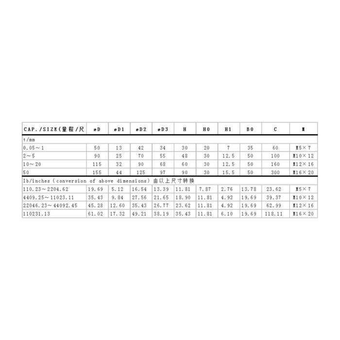
METRAVON MV-LC0036 is a low-profile compression load cell for force measurement and process weighing where a tall support cannot be accommodated. Its circular body uses an integral diaphragm and a raised central loading contact. The technical range is 5-50 t, but there is no single body size for that entire interval. Selecting a rating changes the mechanical envelope; selecting the electrical version changes the required supply and input channel.
Choose the low-profile compression load cell rating before designing the pocket
The metric outline groups several capacities under different dimensions. At the 5 t end of the published technical range, the 2-5 t drawing row gives a 90 mm body diameter and 48 mm height. The 10-20 t row changes these to 115 and 60 mm, while the 50 t row shows 155 and 90 mm. These are drawing references, not an assurance that every intermediate rating is offered. In particular, obtain the rated drawing where no explicit dimension row is provided. Do not enlarge the claimed measurement range merely because the outline table contains lower-capacity rows.
| Item | Value | Selection notes |
|---|---|---|
| 5 t drawing reference | 90 mm diameter / 48 mm height | Uses the 2-5 t metric row; offered rating still needs confirmation. |
| 10-20 t drawing row | 115 mm diameter / 60 mm height | The support and central contact change with the body. |
| 50 t drawing row | 155 mm diameter / 90 mm height | Do not reuse a lower-rating mounting pocket without review. |
| Bridge output / excitation | 2.8 mV/V / 10-12 V DC | Amplified versions require a separately identified supply and wiring. |
| Bridge input / output resistance | 380 +/-10 / 350 +/-5 ohms | Check the weighing reader and any parallel bridge load. |
| Published technical interval | 5-50 t | Lower-capacity outline rows do not extend this specification. |
Separate the bridge from the amplified-output enquiry
The bridge specification is 2.8 +/-0.015 mV/V with 10-12 V DC excitation, 380 +/-10 ohms input resistance and 350 +/-5 ohms output resistance. The feature text also describes three-wire, 24 V, 0-10 V operation; the parameter table separately lists an optional 4-20 mA/24 V DC output. Those entries do not describe one interchangeable terminal arrangement. Ask the quotation to identify the supplied output, supply, wiring, scaling and any integrated or separate conditioner. Do not apply 24 V to the raw bridge or assume that all versions expose both voltage and current outputs.
Leave room for the side enclosure as well as the circular body
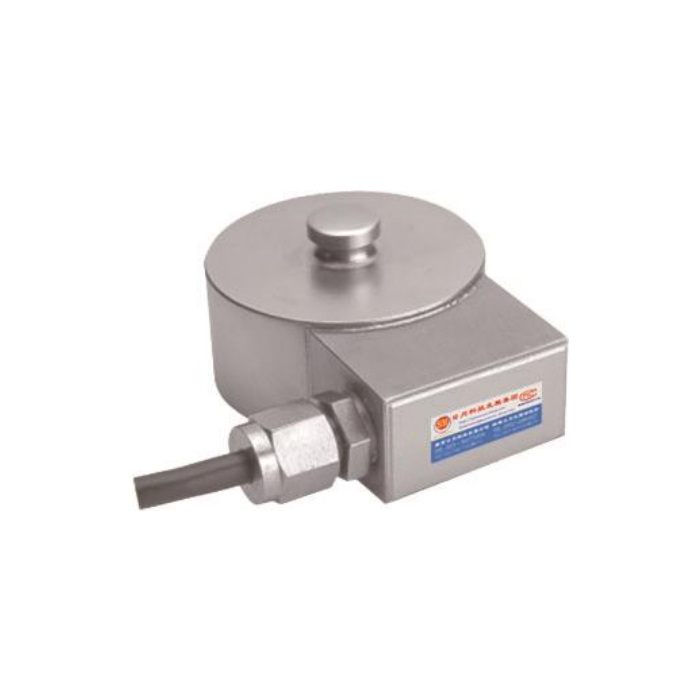
A circular recess drawn only around the sensing body misses the lateral enclosure, gland and cable. Supply a plan and section showing the central contact, base support and cable route. The central contact must carry the intended compression without surrounding brackets sharing the force. Confirm the supported underside and fixing details from the selected outline. The integral diaphragm does not make the housing a general-purpose clamp block, and the cable gland must remain accessible without pulling the cable against the enclosure.
Judge small batch changes against the selected full scale
Reference precision is 0.05% FS. Assess that full-scale basis against the useful material increment, not just the total vessel weight. Vessel tare, residual contents and unequal support reactions can consume much of the available capacity before a batch begins. State both the largest expected reaction and the smallest change that will trigger a process decision. Temperature effect is listed as 0.05% FS per 10 deg C, with operation from -40 to +85 deg C; a wide operating interval is not a promise of unchanged zero through that interval.
Check the completed support and the delivered signal together
Inspect the contact and base before recording unloaded readings, then load through the actual contact part and compare repeated readings and return after unloading. Test the final controller scaling only after the supplied electrical version is identified. The reference lists IP67/IP68 alternatives, so the order must state the delivered enclosure protection and actual water exposure. The 200% FS safe-load entry is not an instruction to overload the installation during acceptance. Specify alloy steel or stainless steel and any cleaning or corrosion conditions rather than assuming that one material suits every process.
Output selection and restricted installation space
Q1. Can I order a 24 V version for a PLC voltage input?
The reference mentions three-wire 0-10 V operation at 24 V, but also documents a raw bridge and an optional current output. Request explicit confirmation of the voltage-output build, terminal functions and scaling. The bridge unit cannot be substituted and powered the same way.
Q2. Why is the side enclosure important in a low-height installation?
It extends beyond the circular body and needs gland and cable access. Include it in the mounting section and reserve a route that does not transmit cable tension into the sensor. A pocket that clears the main diameter alone can still prevent installation or service.
Q3. What should accompany an enquiry for a batching vessel?
Give tare, contents and maximum local support reaction, then add useful batch increments and the available height and plan space. Identify the required signal at the controller. Ask for the rated mechanical drawing and electrical version on the same offer so that the support and reader are selected for the same unit.
