


 Chinese
 Spanish
 Russian
 Portuguese
 French
 German
 Indonesian
 Thai
 Vietnamese
 Arabic
 Italian
 Turkish
 Polish
 Japanese


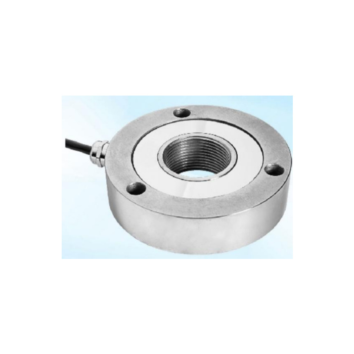

METRAVON MV-LC0035 is a low-profile spoke load cell reference for restricted-height force fixtures. Before selecting it, resolve the centre connection: the reference photograph shows a threaded-looking centre, while the outline uses a diameter callout for a bore. Those views are not enough to approve one interchangeable contact arrangement. Ask for a single model-specific rated section that identifies the delivered centre, load direction and fixing pattern.
Confirm the low-profile spoke load cell centre before choosing an adaptor
A centre thread, a clear bore and a raised bearing annulus need different mating parts. State whether the fixture needs a screwed load fitting, a passing member or a direct compression contact. Have the offer define the actual thread or bore, its tolerances and the permitted force-transfer surfaces. Do not select an adaptor from the apparent thread in a photograph, or use a diameter-labelled opening as permission to tap a thread into the sensor. Any retained fitting should be reviewed on a section drawing.
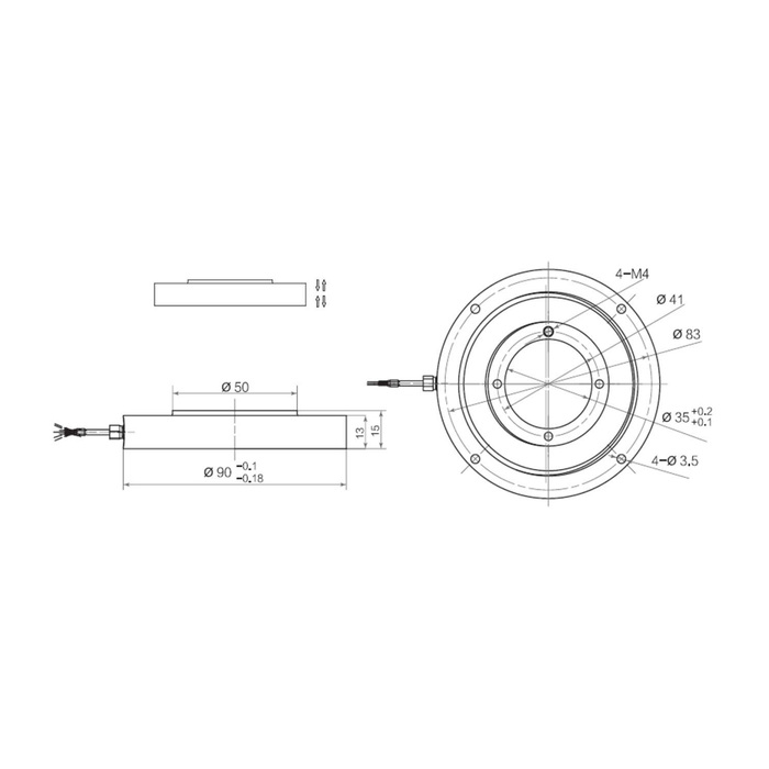
Use the thin outline as a fit reference, not an accepted rated assembly
The outline shows a 90 mm outside-diameter reference, 13 and 15 mm vertical references, and a diameter-50 raised feature. It also carries four M4 and four diameter-3.5 callouts on separate patterns. These features must be reconciled with the offered build before a base or loading part is machined. The overall fixture height includes the required contact and retention parts, not just the thin sensing body. Do not infer a fastener torque, centre-thread size or structural side-load rating from these geometry references.
| Item | Value | Selection notes |
|---|---|---|
| Centre interface | Thread or bore to be confirmed | The photograph and diameter-labelled outline do not settle one build. |
| Outside-diameter reference | 90 mm | Obtain rated dimensions and tolerances before making the pocket. |
| Vertical outline references | 13 / 15 mm | They do not include every required contact or retention part. |
| Raised-feature diameter | 50 mm | Confirm its actual force-transfer role on the delivered section. |
| Fixing callouts | Four M4 / four 3.5 mm holes | Identify their functions and patterns rather than treating them as one set. |
| Rated load and precision | Written model-specific confirmation | Do not transfer conflicting values into the purchase order. |
Put the rated load and precision on the same model-specific confirmation
The available rating and precision entries do not establish one consistent specification for this centre arrangement. Confirm both for the offered build before releasing the order. Provide maximum force, fixture dead load and the smallest useful increment, then ask the offer to state the actual rated load, full-scale precision basis and matching drawing. A similar spoke-type name or a thin body cannot justify borrowing the larger rating or smaller error figure of another sensor. Confirm the required loading direction and whether both directions must be calibrated.
Identify the bridge build and the final reader
The electrical reference gives 2.0 +/-0.015 mV/V with 10-12 V DC excitation, 780 +/-20 ohms input and 700 +/-5 ohms output resistance. Require those channel details to be confirmed for the actual offered unit alongside its mechanical identity. A display or PLC needs an appropriate strain-gauge input or conditioner. Obtain the delivered terminal functions rather than copying wire colours, because the reference legend and circuit differ in signal polarity. Calibration belongs to the assembled fixture, including the final contact part and cable restraint.
Check the contact arrangement before accepting a thin fixture
A small installation gap can encourage direct clamping of surfaces that were intended to remain free. Mark the fixed support, loaded contact and all required clearance in the installation section. Apply the agreed reference forces through that arrangement and compare readings after unloading and refitting any removable adaptor. Include the actual wash or water exposure and requested material in the enquiry; do not treat a general IP67 reference as a cleaning-pressure approval. Release the order only when the rated sheet, drawing and supplied parts describe the same unit.
Centre identity, capacity confirmation and stack height
Q1. Can I order this as a threaded-centre sensor from the photograph?
The photograph alone is insufficient to specify thread form, engagement or approved force direction. Ask for the delivered centre section and corresponding rated sheet. Do not fabricate the adaptor until those documents identify the same build.
Q2. When can a rated load be put on the order?
First reconcile the model-specific rating with its centre arrangement and drawing. Supply the required force and useful increments so the offer can state the confirmed rating and precision. Selecting the largest nearby number would not provide a reliable order specification.
Q3. Will a 15 mm gap contain the complete installation?
The outline has a 15 mm vertical reference, but a working fixture also needs its approved contacts, mounting and retention. Obtain the complete installed section and clearances. Do not force a contact part into an undersized gap or remove sensing-body material to make it fit.
