


 Chinese
 Spanish
 Russian
 Portuguese
 French
 German
 Indonesian
 Thai
 Vietnamese
 Arabic
 Italian
 Turkish
 Polish
 Japanese


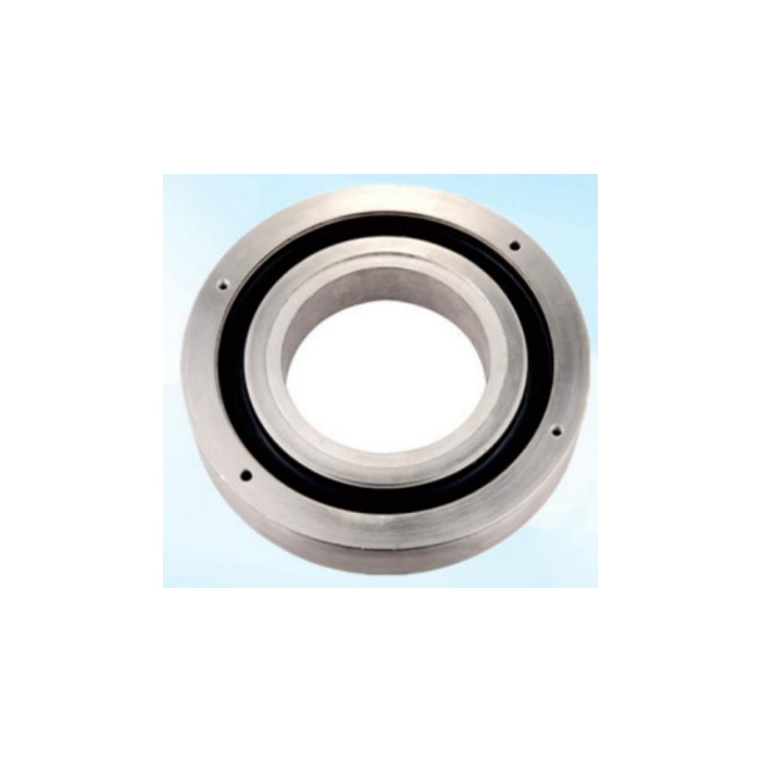

METRAVON MV-LC0034 is a through-bore spoke load cell for an annular force-transfer arrangement. A shaft or tie element can occupy the centre opening only if it remains clear of the sensing surfaces as intended by the fixture design. This differs from assuming that every round spoke cell has a threaded centre. For a test assembly, define the annular bearing areas and clearances before choosing a rating or making a mounting plate.
Keep the through-bore spoke load cell clear of the passing member
Show the diameter, runout and possible movement of the shaft or tie element through the bore. A centre opening is not a bearing or a lateral guide unless the approved assembly explicitly makes it one. The intended force should reach the specified annular contact, without a shoulder or sleeve bridging directly to the fixed support. Ask for the mating contact widths and surface requirements. The reference drawing gives a 40 mm thickness, but that alone does not establish the assembled stack height with load rings and adaptors.
Do not merge the inner and outer fixing features
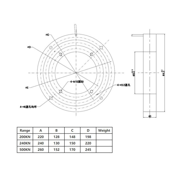
The outline carries separate four-position M10 depth-20, diameter-9 through-hole and diameter-3.2 through-hole callouts. They are not one common bolt size or an approval to use every opening as a structural fixing. Identify each feature and its circle on the rated drawing. The 200 kN dimensional row gives A = 220, B = 128, C = 148 and D = 198 mm; the 240 and 500 kN rows change those dimensions. Keep the lettered geometry with its complete view rather than using an isolated number as a drilling template.
| Item | Value | Selection notes |
|---|---|---|
| Reference form | Annular body with clear centre | Define clearance and annular bearing faces in the fixture section. |
| Outline thickness | 40 mm | Add approved contact parts when defining total stack height. |
| 200 kN row: A / B | 220 / 128 mm | Use the full lettered view and confirm the offered rated version. |
| 200 kN row: C / D | 148 / 198 mm | Not a substitute for identifying each fixing feature. |
| Precision / temperature effect | 0.1% FS / 0.1% FS per 10 deg C | Do not substitute the 0.05% entries of other spoke models. |
| Rated signal / excitation | 2.0 mV/V / 10-12 V DC | Confirm reader compatibility and delivered terminal functions. |
Resolve force units before linking a rating to the outline
The dimensional table is labelled in kN, whereas the technical range entry is 5-50 t. Do not treat equal-looking numbers in those two units as the same load or assign a dimensional row from a broad range label. Require the quotation to name the offered force or mass-based rating and attach its exact dimensional row. Where the assembly uses a tie rod, have its force direction and retention approved separately; a clear bore does not by itself qualify the sensor for tension or bolt-preload measurement.
Use the stated 0.1% full-scale reference, not a neighbouring model value
This model lists 0.1% FS precision and 0.1% FS per 10 deg C temperature effect. Some adjacent spoke models use different entries, which must not be copied into this specification. Bridge output is 2.0 +/-0.015 mV/V, with 780 +/-20 ohms input and 700 +/-5 ohms output resistance at 10-12 V DC. Specify the useful force interval, reader and reference method. A matching nominal sensitivity does not settle the mechanical contacts or the installed error.
Test the complete annular contact arrangement
Apply agreed reference forces through the final rings and passing member, then compare repeated loading and return after removal. Check that clearance remains under the permitted movement and that cables or guards do not create another reaction. For IP67 and alloy-steel or stainless-steel selection, identify the actual water, cleaning and corrosion conditions. The operating interval is -40 to +85 deg C. Keep the 200% FS safe-load entry separate from the strength approval of the fixture and its tie elements.
Clearance, fixing roles and specified precision
Q1. Can a tie rod touch the bore while the force is measured?
Do not assume that contact is allowed. Provide rod movement and clearances for approval, and keep the specified force path through the annular contact. Rubbing or an unintended shoulder can divert force and make the result depend on fixture position.
Q2. Which hole pattern carries the mounting reaction?
The drawing shows several different callouts. Have the selected rated view identify their functions and the approved supporting faces. Neither a through-hole nor a visible thread proves its allowable structural role without the assembly definition.
Q3. Is the precision the same as the other 2 mV/V spoke cells?
This reference lists 0.1% FS, and its temperature-effect entry is also model-specific. Nominal bridge sensitivity does not determine precision. Use this model specification and the installed test requirements rather than copying a neighbouring product table.
